Operation
EL6910
26
Version: 1.8.0
Note the connection of the power contacts
During the design of a Bus Terminal block, the pin assignment of the individual Bus Terminals must
be taken account of, since some types (e.g. analog Bus Terminals or digital 4-channel Bus Termi-
nals) do not or not fully loop through the power contacts.
Potential supply terminals (EL91xx, EL92xx) interrupt the power contacts and thus represent the
start of a new supply rail.
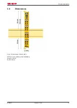
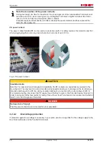
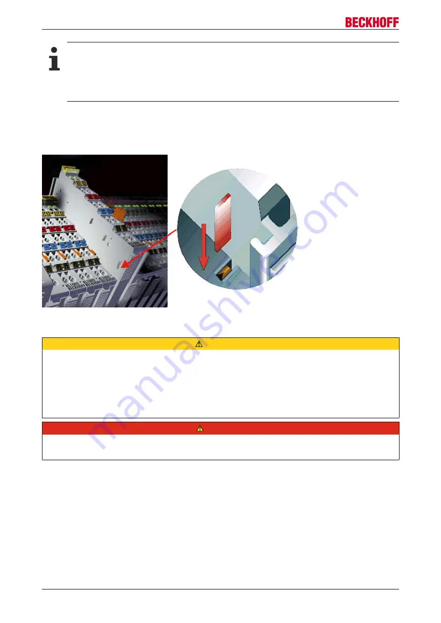
PE power contact
The power contact labelled PE can be used as a protective earth. For safety reasons this contact mates first
when plugging together, and can ground short-circuit currents of up to 125 A.
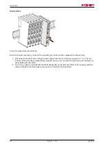
Fig. 9: PE power contact
CAUTION
Insulation tests
Note that, for reasons of electromagnetic compatibility, the PE contacts are capacitatively coupled to the
mounting rail. This may lead to incorrect results during insulation testing or to damage on the terminal (e.g.
disruptive discharge to the PE line during insulation testing of a consumer with a rated voltage of 230 V).
For insulation testing, disconnect the PE supply line at the Bus Coupler or the Potential Supply Terminal! In
order to decouple further feed points for testing, these Power Feed Terminals can be released and pulled at
least 10 mm from the group of terminals.
DANGER
Serious risk of injury!
The PE power contact must not be used for other potentials!
4.2.4.2
Overvoltage protection
If protection against overvoltage is necessary in your plant, provide a surge filter for the voltage supply to the
Bus Terminal blocks and the TwinSAFE terminals.
Summary of Contents for TwinSAFE EL6910
Page 1: ...Operation Manual for EL6910 TwinSAFE Logic Terminal 1 8 0 2019 01 09 Version Date...
Page 2: ......
Page 69: ...Operation EL6910 69 Version 1 8 0 Fig 73 The Safety Project Online View tab...
Page 136: ...Appendix EL6910 136 Version 1 8 0 5 2 Certificates...
Page 137: ...Appendix EL6910 137 Version 1 8 0...


