Foreword
PS2001-2410-0000
8
Version: 1.0
Safety instructions and installation requirements for PS2001-2410-0000 power supply unit
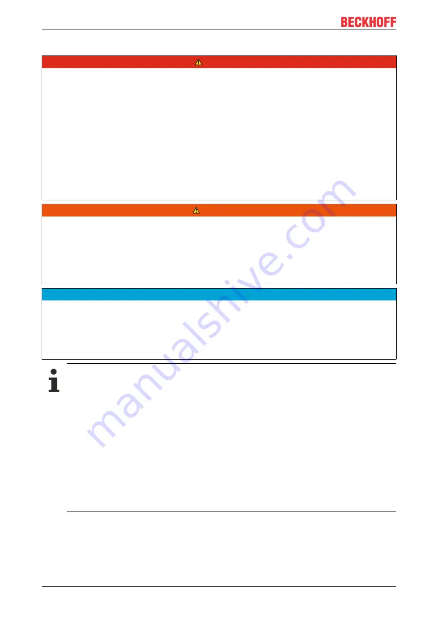
DANGER
Danger of electric shock, fire, injuries, injuries resulting in death!
• Do not use the power supply without proper earthing (protective conductor). Use the terminal at the input
terminal strip for the earth connection, not one of the screws on the housing.
• Switch off the power supply before working on the device. Provide protection against unintentional re-
connection.
• Ensure proper wiring by following all local and national regulations.
• Do not modify or attempt to repair the device.
• Do not open the device, as high voltages are present inside.
• Avoid foreign bodies entering the housing.
• Do not use the device in damp locations or in areas where moisture or condensation is likely to occur.
• Do not touch the device when it is switched on or immediately after it has been switched off. Hot sur-
faces can cause burns.
WARNING
Explosion hazard warning!
Use only in standard vertical mounting orientation with the input terminals at the bottom of the device.
Replacement of components may affect the suitability for this environment.
Do not disconnect the device from the mains and do not operate the voltage adjustment unless the power is
switched off or the environment can be considered safe.
For the end product a suitable housing must be provided, which has a minimum protection class of IP54
and meets the requirements of EN 60079-0.
NOTE
Instructions for use in potentially explosive atmospheres
The device is suitable for use in the following areas:
Class I Division 2 Groups A, B, C, D
and for use in Group II environments of Category 3 (Zone 2).
Classification:
ATEX: EPS 15 ATEX 1 101 X, II 3G EX ec nC IIC T4 Gc / IECEx EPS 20.0046X.
Further notes on installation requirements
• This device contains no parts that require maintenance. If an internal fuse trips, this is due to an
internal defect.
• If any damage or malfunction occurs during installation or operation, turn off the power immedi-
ately and return the device to the factory for inspection.
• Mount the device on a DIN rail so that the input terminals are at the bottom of the device. For
other mounting positions, please refer to the load reduction requirements in this document. See
chapter Installation positions.
• This device is designed for convection cooling and does not require an external fan. Do not ob-
struct the air circulation. No more than 15% of the ventilation grille may be covered (e.g. by cable
ducts)!
• Maintain the following installation distances: 40 mm at the top, 20 mm at the bottom and 5 mm
on the left and right are recommended if the device continuously runs at more than 50% of the
rated output. Increase this distance to 15 mm if the adjacent device is a heat source (e.g. an-
other power supply unit).


