–13–
7.0
Calibration
■
NOTE: The M-0245C has been fully calibrated at
the factory using highly sophisticated,
computer-controlled test equipment. There
is no need to recalibrate the unit before
initial installation. Further calibration is only
necessary if a component is changed
during a repair procedure.
Access to the calibration points is only possible with
the top cover removed; therefore, after field repair,
do not install the unit in a rack or panel before following
these procedures.
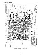
Refer to Figure 2, External Connections, and Figure
6, Component Location.
Phase Angle Calibration
1.
Supply 120 V ac, 60 Hz to TB1-1 and
TB1-2, noting that TB1-1 is the HOT
terminal.
2.
Place a clip lead between TB1-1 and
TB1-4.
3.
Place a second between TB1-2 and TB1-3.
4.
Using a dual trace oscilloscope or phase
meter attach one channel to E3 of the low
pass filter board.
5.
Attach the second channel to E4.
6.
Attach the common lead of the scope or
phase meter to E6.
7.
Adjust R1 of the filter board (B-0246) for a
measured phase angle of 0.00 degrees.
8.
Adjust R196 until the voltmeter reads 6.000
V dc at R50.
9.
Adjust R200 until the voltmeter reads 6.000
V dc at R116.
10.
Remove the clip leads from TB1-1 and
TB1-4 and TB1-2 and TB1-3.
11.
Place a clip lead between TB1-1 and
TB1-3.
12.
Place a second clip lead between TB1-2
and TB1-4
13.
Attach the positive lead of the dc voltmeter
to Test Point 1 (TP1).
14.
Attach the negative lead to TB1-7 or C78
(–) end.
15.
Supply 120 V ac, 60 Hz to power input
TB1-26 and TB1-27, noting TB1-27 is the
HOT terminal.
16.
Adjust R89 until the voltmeter reads
+10.000 volts.
17.
Remove the positive lead of the dc
voltmeter and attach to Test Point 2 (TP2).
18.
Adjust R6 until the voltmeter reads –10.014
volts.
19.
Remove the positive lead of the dc
voltmeter and attach to Test Point 3 (TP3).
20.
Adjust R65 until the voltmeter reads
–10.014 volts.
21.
Remove the positive lead of the dc
voltmeter and attach to R105 or the jumper
between points J and K.
22.
The voltmeter should read +10.00 volts
K
0.03 volts.
23.
Adjust source supplying TB1-1 and TB1-2
to 60.000 Hz.
24.
Remove clip leads to TB1-3 and TB1-4,
supply 60 Hz at +90°, 120 V ac to TB1-3
and TB1-4, TB1-4 being HOT.
25.
Record voltmeter reading.
26.
Change phase angle of source to TB1-3
and TB1-4 to 90°.
27.
The voltmeter reading should be about
K
.05 V of the recorded voltage.
Summary of Contents for M-0245C
Page 1: ...Instruction Book M 0245C High Speed Sync Check Relay ...
Page 23: ... 14 M 0245C Instruction Book Figure 6 Component Location B 0207 ...
Page 24: ... 15 Figure 7 Variable Speed Motor Application Component Location B 0264 ...
Page 25: ... 16 M 0245C Instruction Book ...
Page 26: ... 17 Figure 8 Schematic X 0245C ...


