– i –
Table of Contents
M-0245C High Speed Sync-Check Relay
Instruction Book
1.0
Introduction ................................................................................................................... 1
2.0
Theory of Operation ...................................................................................................... 1
Motor Bus Undervoltage Monitor .................................................................................. 1
Input Loss Protection .................................................................................................... 1
3.0
Maintenance ................................................................................................................. 2
Figure 1
Block Diagram ............................................................................................. 3
4.0
Test Procedure ............................................................................................................. 4
Equipment Required ..................................................................................................... 4
4.1
Component Replacement Procedure ........................................................................... 4
4.2
Test Procedures ........................................................................................................... 4
Upper Voltage Limit ...................................................................................................... 4
Lower Voltage Limit ...................................................................................................... 4
Phase Angle Limit ......................................................................................................... 5
Voltage Analog Output .................................................................................................. 5
Phase Angle Analog Output ......................................................................................... 5
Voltage Status Output Contact ..................................................................................... 5
Figure 2
External Connections ................................................................................... 6
Phase Angle Status Output .......................................................................................... 7
Breaker Close Circuit .................................................................................................... 7
Enable Response Time ................................................................................................ 7
Phase Angle OK to Output Contact Response Time .................................................... 8
4.3
Phase Angle Detection Circuit ...................................................................................... 8
Rate of Change of Phase Angle ................................................................................... 8
4.4
Loss of Voltage Input Detection Circuits ....................................................................... 8
Line Voltage Loss ......................................................................................................... 8
Motor Bus Voltage Loss ............................................................................................... 8
Motor Bus Undervoltage Detector <25% ...................................................................... 8
Figure 3
Test Setup ................................................................................................... 9
Figure 4
Line Voltage Loss ...................................................................................... 10
Figure 5
Motor Bus Voltage Loss ............................................................................. 10
5.0
Typical Voltages ......................................................................................................... 11
Conditions ................................................................................................................... 11
6.0
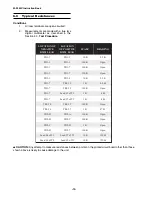
Typical Resistances ................................................................................................... 12
Conditions ................................................................................................................... 12
Summary of Contents for M-0245C
Page 1: ...Instruction Book M 0245C High Speed Sync Check Relay ...
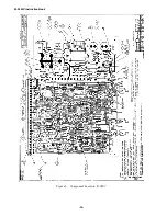
Page 23: ... 14 M 0245C Instruction Book Figure 6 Component Location B 0207 ...
Page 24: ... 15 Figure 7 Variable Speed Motor Application Component Location B 0264 ...
Page 25: ... 16 M 0245C Instruction Book ...
Page 26: ... 17 Figure 8 Schematic X 0245C ...


