OPERATING PRINCIPLES
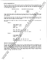
In order to understand the operation of the microprocessor-based relay, refer to the Functional Diagram
shown in Figure
1.
This diagram indicates the mix of hardware
and
software and represents the software
in a logical form, but does not represent the actual mechanization of the relays or the flow of the
program. However, it is useful in understanding how the various relaying functions are combined, the.
hardware/software mix, and the overall operation of
the
unit.
n>e
M-0290
uses a low-cost
Ac!Dc
converter and analog level detectors for the over and undervol tage
detection.
This provides an economical design at the expense of accuracy and flexibility in changing
the OVer
and
Undervoltage setpoints. The Single-phase OVer
and
Undervoltage setpoints are determined by
precision resistors in the over and undervol tage cireui ts.
These resistors can
be
changed by
the
user
if settings other than those ordered are desired.
See
Table
2
under the FIELD
AnJUSTMEm'
sectiolla
The
over and under frequency relaying and the time delays are implemented in the microprocessor software.
'!be
limit settings for the software functions are stored in the processor memory.
In order to change
these settings, the memory circuit board can be exchanged o r the settings can be altered by the
customer using the optional Field Adjustment Unit
M-0297/M-03 97.
Refer to the FIELD
l\IlJU
STMENT
section
for a complete description of this prooedur�
The frequency calculations require reliable reproduction of the period of the input ac potentials.
Input Loss detection is used to determine if sufficient potential or senSing input voltage is available
for a reliable measurement of frequency.
Two tn:es of Input Loss Detection are incortx>rated in the software of the PRIDE®Units.
1 .
Any f requency measurement above
80
Hz and below
40
Hz will be ignored. This is the Frequency
Blocked State
and
will
be
indicated by both frequency
LEOs
turning on.
2 .
If n o zero-crossings a r e detected for approximately
0.5
sec o r if the voltage falls below
0.45
p.o., the frequency measurement will also
be
blocked: therefore, frequency cannot initiate trip
ping. The reason for this implementation is to allow
the
undervoltage condition to trip the relay.
If the voltage input is lost or if a "noisy" loss occurs and the Under Freq uency Trip Timer is set
extremely low
(1
to
3
cycles), there may
be
a chance thst the Under Frequency Trip Timer may time out
before the loss can be detected and the freq uency timers can be blocked. Refer to the section on
ClIOOSIN3
LIMIT
SETrIN3S
for recommended Trip Timer settings.
The frequency will also
be
blocked if the
�
of change of frequency (6F) is greater than
1
Hz/cycle
in successive period measurements. This �F Transient Protection will prevent noise spikes f rom
triggering the frequency timers.
'Ihe frequency flIDctions use a counter in the microprocessor to determine the period of the input.
The
period is calculated after each cycle.
A
digital filter in the processor software filters the period
data t9 reduce the effect of phase jitter on the measurement. The filtered period data is then
compared to the upper and lower limits stored in the processor memory.
Since the period is the
reciprocal of frequency, the OVer/Under Frequency function is accomplished.
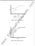
Dynamic hystereSis is incorIX>rated in the frequency measurement routine. While the trip point always
remains absolute. the point where the frequency returns within the setpJint range will vary as follows:
Fr
=
FS
Fs
(.002083)
+
0 .875
Where: F s
=
OVer or Under Frequency setpoint (Hz)
F r
=
Frequency return point (Hz)
-3-
( 1)
www
. ElectricalPartManuals
. com


