The Block Diagram for the M-0290 is shown in Figure 5. The following discussion describes the basic
operation of the circuitry.
INPUTS
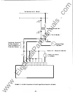
Power is aw1ied to the PRIDE�via rear terminals 'll31-3 and 'lB1-4. The PRIDE
can
be powered from either
ac or de sources as described below. The SenSing input (TBl-5 and
TBl-6)
is used only for measurement
purposes and draws only a small burden. However, in many cases, the
ac
power input will be conn::cted
to the Sensing input, due to the lack of a separate ac power source.
Ac Supply
The Ac Supply PRIDE Units operate from a 120
V
ac source. If this is unavailable, the Dc Supply,
described below, may be ordered for the PRIDE.
Dc Supply
ihe
Dc
Supply mounts in the bottom compartment of the PRIDE (see Figures 7 and 16). Three nominal dc
voltage options are available: 125
V
dc, 48
V
dc or 24
V
dc. The PRIDE will operate from approximately
65% of the nominal voltage to 128% of the nom inal voltage (i.e., 80 to 160
V
dc for the 125
V
dc
option). Operation from 250
V
dc is possible, but requires
an
M-0319 external Dropping Regulator to
provide 125
V
dc nominal input voltage to the PRIDE.
The M-0290 should be ordered for 125
V
dc
operation and the M-0319 is ordered separately. The M-0319 is a resistor-zener diode regulating device
used to produce 125
V
dc power from a 250
V
dc battery source.
POWER
SUPPLY
The Power Supply provides the voltages necessary for operation of the digital and
analog
circuits. A
Power Loss Detector is incorporated to warn if the the power supply fails. The Power Loss Detector
feature is described in detail below.
Power Loss Det ector
When
the power suWly fails, the input power is lost, or if the input power fuse blows, the Power Loss
Detector will:
1. Reset the microprocessor.
2. De-energize the
Kl
output relay (this will be the Trip State in the Standard Relay Configuration
and the Close State in the Alternate or Pulse Relay Configuration>.
3
•
Turn off the front panel
rowER
OK LED.
4 . De-energize the normally closed K4 Power Loss relay.
This contact
can
be used to sound or light
an alarm.
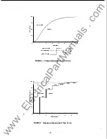
The time delay between when the Power Loss Detector senses a loss and when the
Kl
output relay is
de
energized is shown in Figure
6. The
data was taken bY connecting the power input to
the
Phase A input
of the
PRIDE
ihree-Pbase M-0296. A similar curve
can
be expected with data taken for the M-0290. The
phase A input was dropped from 120
V
ac to levels pe r the graph, and the time delay for tripping was
measured.
When
the input dropped below approximately 75
V
ac,
the
PRIDE
trip time dropped to 0.25 sec.
This is the level where the internal power supply voltage is below its minimum operating level and
the
Power Loss Detector resets the
PRIDE
.
Therefore, if the input power drops to this level, the
PRIDE
may
trip faster
than
the programmed time (3 sec in this case).
If this feature is not desirable, the ca!"citor Power Hold-Up Option, described below, is available for
the
PRIDE.
- 1 1 -
www
. ElectricalPartManuals
. com


