1
3
A
B
C
4–15
Remote Operation – 4
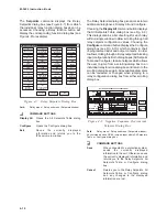
The Oscillograph submenu allows storing data on
selected parameters for review and plotting at a
later time. The Setup command allows the user to
set the number of partitions and triggering
designations to be made. The Retrieve command
downloads and stores collected data to a file; Trigger
allows the manual triggering of the recorder; Clear
erases the existing records. Run the optional
M-3801C IPSplot
®
Oscillograph Analysis Software
program to view the downloaded oscillograph files.
Profile is currently unavailable, and will be greyed-
out in display.
Setup
4
Monitor
4
Targets
4
Oscillograph
4
Profile
4
Write File to Relay
Read Data from Relay
Relay
Setup
Retrieve
Trigger
Clear
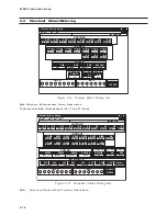
The Write File To Relay command is used to write
the data to the relay. The Read Data From Relay
command is used to retrieve the data from the relay
to the computer for display.
Setup
4
Monitor
4
Targets
4
Oscillograph
4
Profile
4
Write File to Relay
Read Data from Relay
Relay
Window Menu/Help Menu
Window
Cascade
Tile
Arrange Icons
Close All
The Window menu enables the positioning and
arrangement of all IPScom
®
windows so that there
is better access to available functions. This feature
allows the display of several windows at the same
time. Clicking on an inactive window activates that
window.
Currently in revision, the Help menu will enable the
user to look up information about any IPScom
menus or commands. Though displaying (greyed-out)
Help commands, this menu item is currently
unavailable.
Contents
Using Help
About...
Profile Info
Help
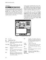
The About IPScom Dialog Box (see Figure 4-13)
displays IPScom version and development
information.
About IPScom
x
IPScom
s
Integrated Protection System
Version: D-0055V1.3.1
Copyright
a
1997-99 Beckwith Electirc Co., Inc.
OK
Unit Information
Serial Number
Software Version
Communication Address
Control Number
Setpoint Checksum
Calibration Checksum
ID
IPS
Figure 4-13
About IPScom Dialog Box
Path:
Help menu / About... command
COMMAND BUTTONS
OK
Exits the currently displayed dialog box.
The Profile Info will allow the user to view or make
notations for the relay setpoint data files. This
command is currently unavailable, and will be
greyed-out in the display.
Summary of Contents for M-3425
Page 1: ...Instruction Book M 3425 Generator Protection ...
Page 14: ... 13 M 3425 Generator Protection Relay Figure 1 External Connections ...
Page 33: ...x M 3425 Instruction Book This Page Left Intentionally Blank ...
Page 89: ...M 3425 Instruction Book 2 52 This Page Left Intentionally Blank ...
Page 125: ...1 3 A B C M 3425 Instruction Book 4 26 This Page Left Intentionally Blank ...
Page 187: ...M 3425 Instruction Book 6 50 This Page Left Intentionally Blank ...
Page 207: ...M 3425 Instruction Book C 4 This Page Left Intentionally Blank ...
Page 209: ...D 2 M 3425 Instruction Book Figure D 1 Volts Hz 24 Inverse Curve Family 1 Inverse Square ...
Page 210: ...Inverse Time Curves Appendix D D 3 Figure D 2 Volts Hz 24 Inverse Family Curve 2 ...
Page 211: ...D 4 M 3425 Instruction Book Figure D 3 Volts Hz 24IT Inverse Curve Family 3 ...
Page 212: ...Inverse Time Curves Appendix D D 5 Figure D 4 Volts Hz 24IT Inverse Curve Family 4 ...
Page 215: ...D 8 M 3425 Instruction Book Figure D 5 Definite Time Overcurrent Curve ...
Page 216: ...Inverse Time Curves Appendix D D 9 Figure D 6 Inverse Time Overcurrent Curve ...
Page 217: ...D 10 M 3425 Instruction Book Figure D 7 Very Inverse Time Overcurrent Curve ...
Page 218: ...Inverse Time Curves Appendix D D 11 Figure D 8 Extremely Inverse Time Overcurrent Curve ...
Page 223: ...D 16 M 3425 Instruction Book This Page Intentionally Left Blank ...


