M-3425 Instruction Book
6–12
3.
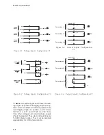
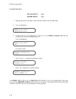
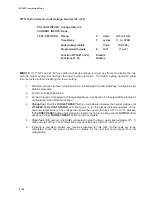
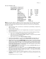
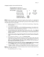
Connect V
A
= V
B
= V
C
= V
N
=
120.0(±0.01)V at 0° phase. (See Figure
6-12.)
4.
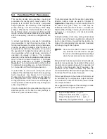
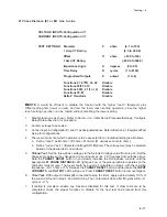
Connect I
a
=I
b
=I
c
=I
A
=I
B
=I
C
=I
N
=5.00**
Amps at 0° (see Figure 6-11).
**
For a 1 A CT rating, use 1 A.
The calibration can be verified by reading status:
V
A
=V
B
=V
C
=V
N
=120V
V
1
=V
2
=0
V
0
=120V
I
A
=I
B
=I
C
=5 A**
I
1
=I
2
=0
I
0
=5 A*
I
a
=I
b
=I
c
=5 A*
Real=1 pu Reactive=0.0 pu
Power Factor = 1.0
I
diffa
= I
diffb
= I
diffc
= 0
Where subscript 0, 1, and 2 represent zero, positive,
and negative sequence quantities, respectively.
**
For a 1 A CT rating, use 1 A.
■
■
■
■
■
NOTE: The phase angle difference between
voltage and current input source should
be 0°, K0.05°, and an accurate low-
distortion source should be used. (THD
less than 1%).
5.
Press ENTER. The display will show
WAIT while the relay is being calibrated.
When calibration is complete, the display
will read CONNECT 180 Hz INPUTS
(150 Hz for 50 Hz models).
6.
Remove the calibration source inputs. If
you wish to calibrate the third harmonic,
continue to Third Harmonic Calibration.
If not, press EXIT to exit calibration
mode.
Third Harmonic Calibration
1.
If the user wishes to calibrate the third
harmonic only, follow the Step #1 and #2
procedures for calibration (above), and
press the down arrow when the display
reads CONNECT 60 Hz INPUTS. The
display will then read CONNECT 180 Hz
INPUTS (150 Hz for 50 Hz models).
2.
Connect V
N
=10 V, 180 Hz (150 Hz for 50
Hz units). See Figure 6-12.
3.
Press ENTER. The display will show
WAIT while the third harmonic is
calibrated. When calibration is complete,
it will show DONE.
4.
Remove the voltage from V
N
.
Field Ground Calibration
Field Ground Calibration only applies to units
purchased with the 64F Field Ground option.
Calibration is necessary for long cable lengths
(greater than 100 feet) to compensate for cabling
losses from the M-3425 and the M-3921 Coupler
module, and therefore should be accomplished in
system, after all wiring is complete.
Summary of Contents for M-3425
Page 1: ...Instruction Book M 3425 Generator Protection ...
Page 14: ... 13 M 3425 Generator Protection Relay Figure 1 External Connections ...
Page 33: ...x M 3425 Instruction Book This Page Left Intentionally Blank ...
Page 89: ...M 3425 Instruction Book 2 52 This Page Left Intentionally Blank ...
Page 125: ...1 3 A B C M 3425 Instruction Book 4 26 This Page Left Intentionally Blank ...
Page 187: ...M 3425 Instruction Book 6 50 This Page Left Intentionally Blank ...
Page 207: ...M 3425 Instruction Book C 4 This Page Left Intentionally Blank ...
Page 209: ...D 2 M 3425 Instruction Book Figure D 1 Volts Hz 24 Inverse Curve Family 1 Inverse Square ...
Page 210: ...Inverse Time Curves Appendix D D 3 Figure D 2 Volts Hz 24 Inverse Family Curve 2 ...
Page 211: ...D 4 M 3425 Instruction Book Figure D 3 Volts Hz 24IT Inverse Curve Family 3 ...
Page 212: ...Inverse Time Curves Appendix D D 5 Figure D 4 Volts Hz 24IT Inverse Curve Family 4 ...
Page 215: ...D 8 M 3425 Instruction Book Figure D 5 Definite Time Overcurrent Curve ...
Page 216: ...Inverse Time Curves Appendix D D 9 Figure D 6 Inverse Time Overcurrent Curve ...
Page 217: ...D 10 M 3425 Instruction Book Figure D 7 Very Inverse Time Overcurrent Curve ...
Page 218: ...Inverse Time Curves Appendix D D 11 Figure D 8 Extremely Inverse Time Overcurrent Curve ...
Page 223: ...D 16 M 3425 Instruction Book This Page Intentionally Left Blank ...


