Communications: Appendix – B
B–1
B
Appendix B–Communications
The M-3425 Generator Protection Relay
incorporates three serial ports for intelligent, digital
communication with external devices. Equipment
such as RTU's, data concentrators, modems, or
computers can be interfaced for direct, on-line, real
time data acquisition and control. Generally, all
data available to the operator through the front
panel of the relay with the optional M-3931 Human-
Machine Interface module is accessible remotely
through the BECO 2200 or MODBUS data
exchange protocol. These protocol documents and
the database-specific protocol document are
available from the factory or from our website at
www.beckwithelectric.com.
The M-3820A IPSCom
®
Communication Software
package has been supplied for communication to
any IBM compatible computer running under
Microsoft
®
Windows 95 or higher.
The communcation protocols implement serial, byte
oriented, asynchronous communication and can
be used to fulfill the following communications
functions:
•
Real time monitoring of line status.
•
Interrogation and modification of setpoints.
•
Downloading of recorded oscillograph
data.
•
Reconfiguration of relay functions.
■
■
■
■
■
NOTE: The following restrictions apply for
MODBUS protocol use:
1.
MODBUS protocol is not supported on
COM1.
2.
Parity is supported on COM2 and COM3;
valid selections are 8,N,2; 8,O,1 or 8,E,1.
3.
ASCII mode is not supported (RTU only).
4.
Standard baud rates from 300 to 9600
are supported.
5.
Only the following MODBUS commands
are supported:
a. read holding register (function 03)
b. read input register (function 04)
c. force single coil (function 05)
d. preset single register (function 06)
For detailed information on IPScom
communications, refer to Chapter 4, Remote
Operation.
Communication Ports
The relay has both front and rear panel RS-232
ports and a rear RS-485 port. The front and rear
panel RS-232 ports are 9-pin (DB9S) connector
configured as DTE (Data Terminal Equipment) per
the EIA-232D standard. Signals are defined in Table
B-1, Communication Port Signals .
The 2-wire RS-485 port is assigned to the rear
panel terminal block pins 3 (–) and 4 (+).
Each communication port may be configured to
operate at any of the standard baud rates (300,
600, 1200, 2400, 4800, and 9600). The RS-485
port shares the same baud rate with COM 2 (for
COM1 see Section 5.4, Circuit Board Switches and
Jumpers).
While the digital communication ports do include
some ESD (Electrostatic Discharge) protection
circuitry, they are excluded from passing ANSI/
IEEE C37.90.1-1989. Beckwith Electric
recommends the use of RS-232/485 to fiber optic
converters to avoid any question of surge-withstand
capability or ground potential rise.
A null modem cable is also shown in Figure B-1,
Null Modem Cable: M-0423, if direct connection to
a PC (personal computer) is desired.
Summary of Contents for M-3425
Page 1: ...Instruction Book M 3425 Generator Protection ...
Page 14: ... 13 M 3425 Generator Protection Relay Figure 1 External Connections ...
Page 33: ...x M 3425 Instruction Book This Page Left Intentionally Blank ...
Page 89: ...M 3425 Instruction Book 2 52 This Page Left Intentionally Blank ...
Page 125: ...1 3 A B C M 3425 Instruction Book 4 26 This Page Left Intentionally Blank ...
Page 187: ...M 3425 Instruction Book 6 50 This Page Left Intentionally Blank ...
Page 207: ...M 3425 Instruction Book C 4 This Page Left Intentionally Blank ...
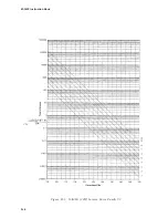
Page 209: ...D 2 M 3425 Instruction Book Figure D 1 Volts Hz 24 Inverse Curve Family 1 Inverse Square ...
Page 210: ...Inverse Time Curves Appendix D D 3 Figure D 2 Volts Hz 24 Inverse Family Curve 2 ...
Page 211: ...D 4 M 3425 Instruction Book Figure D 3 Volts Hz 24IT Inverse Curve Family 3 ...
Page 212: ...Inverse Time Curves Appendix D D 5 Figure D 4 Volts Hz 24IT Inverse Curve Family 4 ...
Page 215: ...D 8 M 3425 Instruction Book Figure D 5 Definite Time Overcurrent Curve ...
Page 216: ...Inverse Time Curves Appendix D D 9 Figure D 6 Inverse Time Overcurrent Curve ...
Page 217: ...D 10 M 3425 Instruction Book Figure D 7 Very Inverse Time Overcurrent Curve ...
Page 218: ...Inverse Time Curves Appendix D D 11 Figure D 8 Extremely Inverse Time Overcurrent Curve ...
Page 223: ...D 16 M 3425 Instruction Book This Page Intentionally Left Blank ...


