Application – 2
2–23
46 Negative Sequence Overcurrent
The Negative Sequence Overcurrent function
provides protection against possible rotor
overheating and damage due to unbalanced faults
or other system conditions which can cause
unbalanced three phase currents in the generator.
Ranges and increments are presented in Table 2-8.
This function has a definite time element and an
inverse time element. The definite time pickup value
and definite operating time are normally associated
with an alarm function. The inverse time element is
usually associated with a trip function and has a
pickup and an operating time defined by an (I
2
)
2
t =
K, where K is the Time Dial Setting and I
2
is the per
unit negative sequence current.
The minimum delay for the inverse time function is
factory set at 12 cycles to avoid nuisance tripping.
A maximum time to trip can be set to reduce the
operating times for modest imbalances. An important
feature that helps protect the generator from damage
due to recurring imbalances is a linear reset
characteristic. When I
2
decreases below the pickup
value, the trip timer takes four minutes to reset from
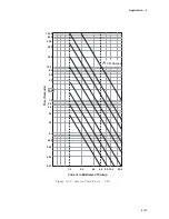
its 100% trip level. Figure 2-12, Negative Sequence
Overcurrent Inverse Time Curves, illustrates the
inverse time characteristic of the negative sequence
overcurrent function.
Operating times are lower than that is shown in
Figure 2-12 when measured current values are
greater than 15 A (3 A for 1 A rated circuit).
The first task of setting this function is to determine
the capabilities of the associated machine. As
established by ANSI standards, the machine limits
are expressed as (I
2
)
2
t = K. The value of K is
established by the machine design and is generally
provided on test sheets of the machine. The relay
can accommodate any generator size because of
the wide range of K settings from 1 to 95. Typical
values can be found in ANSI C50.13-1977.
The negative sequence pickup range is from 3% to
100% of the Nominal Current value input during
system setup (see Section 2.1, Configuration).
This protection must
not operate for system faults
that will be cleared by system relaying. This requires
consideration of line protection, bus differential and
breaker failure backup protections.
N
O
I
T
C
N
U
F
E
G
N
A
R
T
N
I
O
P
T
E
S
T
N
E
M
E
R
C
N
I
)
6
4
(
t
n
e
r
r
u
c
r
e
v
O
e
c
n
e
u
q
e
S
e
v
i
t
a
g
e
N
e
m
i
T
e
t
i
n
i
f
e
D
p
u
k
c
i
P
%
0
0
1
o
t
3
%
1
y
a
l
e
D
e
m
i
T
s
e
l
c
y
C
0
6
1
8
o
t
1
e
l
c
y
C
1
e
m
i
T
e
s
r
e
v
n
I
p
u
k
c
i
P
%
0
0
1
o
t
3
%
1
g
n
i
t
t
e
S
l
a
i
D
e
m
i
T
I
=
K
(
2
2
)
t
5
9
o
t
1
1
m
u
m
i
x
a
M
e
t
i
n
i
f
e
D
p
i
r
T
o
t
e
m
i
T
s
e
l
c
y
C
0
0
5
,
5
6
o
t
0
0
6
e
l
c
y
C
1
e
m
i
T
m
u
m
i
n
i
M
e
ti
n
i
f
e
D
s
e
l
c
y
C
2
1
d
e
x
i
F
)
r
a
e
n
il
(
e
m
i
T
t
e
s
e
R
s
e
t
u
n
i
m
4
)
p
i
r
t
f
o
d
l
o
h
s
e
r
h
t
m
o
r
f
(
–
Table 2-8
Negative Sequence Overcurrent (46) Setpoint Ranges
Summary of Contents for M-3425
Page 1: ...Instruction Book M 3425 Generator Protection ...
Page 14: ... 13 M 3425 Generator Protection Relay Figure 1 External Connections ...
Page 33: ...x M 3425 Instruction Book This Page Left Intentionally Blank ...
Page 89: ...M 3425 Instruction Book 2 52 This Page Left Intentionally Blank ...
Page 125: ...1 3 A B C M 3425 Instruction Book 4 26 This Page Left Intentionally Blank ...
Page 187: ...M 3425 Instruction Book 6 50 This Page Left Intentionally Blank ...
Page 207: ...M 3425 Instruction Book C 4 This Page Left Intentionally Blank ...
Page 209: ...D 2 M 3425 Instruction Book Figure D 1 Volts Hz 24 Inverse Curve Family 1 Inverse Square ...
Page 210: ...Inverse Time Curves Appendix D D 3 Figure D 2 Volts Hz 24 Inverse Family Curve 2 ...
Page 211: ...D 4 M 3425 Instruction Book Figure D 3 Volts Hz 24IT Inverse Curve Family 3 ...
Page 212: ...Inverse Time Curves Appendix D D 5 Figure D 4 Volts Hz 24IT Inverse Curve Family 4 ...
Page 215: ...D 8 M 3425 Instruction Book Figure D 5 Definite Time Overcurrent Curve ...
Page 216: ...Inverse Time Curves Appendix D D 9 Figure D 6 Inverse Time Overcurrent Curve ...
Page 217: ...D 10 M 3425 Instruction Book Figure D 7 Very Inverse Time Overcurrent Curve ...
Page 218: ...Inverse Time Curves Appendix D D 11 Figure D 8 Extremely Inverse Time Overcurrent Curve ...
Page 223: ...D 16 M 3425 Instruction Book This Page Intentionally Left Blank ...


