M-3425 Instruction Book
2–50
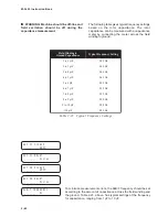
EXT #1 INPUT INITIATE
i6 i5 i4 i3 i2 i1
EXT #1 DELAY
________ Cycles
EXT #2 INPUT INITIATE
i6 i5 i4 i3 i2 i1
EXT #2 DELAY
________ Cycles
External Functions
The M-3425 Generator Protection Relay provides
two “external functions” to allow external device
contacts to trip through the relay. These functions
expand the relay’s capability by providing additional
operating logic and target information for external
devices. The
initiating inputs are designated to
provide external stimulus to start the function. The
designated
blocking inputs and output contacts, as
specified in Section 2.1, Configuration, can be used
to provide additional logic.
N
O
I
T
C
N
U
F
E
G
N
A
R
T
N
I
O
P
T
E
S
T
N
E
M
E
R
C
N
I
s
n
o
i
t
c
n
u
F
l
a
n
r
e
t
x
E
h
g
u
o
r
h
t
p
i
r
t
o
t
s
e
c
i
v
e
d
d
e
t
c
e
n
n
o
c
y
l
l
a
n
r
e
t
x
e
r
o
f
d
e
d
i
v
o
r
p
e
r
a
s
n
o
i
t
c
n
u
f
o
w
T
r
o
e
n
o
y
n
A
.
n
o
i
t
a
m
r
o
f
n
i
t
e
g
r
a
t
d
n
a
c
i
g
o
l
l
a
n
o
i
t
i
d
d
a
e
d
i
v
o
r
p
o
t
5
2
4
3
-
M
e
h
t
d
e
m
m
a
r
g
o
r
p
e
b
n
a
c
)
6
T
U
P
N
I
h
g
u
o
r
h
t
1
T
U
P
N
I
(
s
t
c
a
t
n
o
c
t
u
p
n
i
e
h
t
f
o
e
r
o
m
.
y
a
l
e
d
e
m
i
t
d
e
t
c
e
l
e
s
a
r
e
t
f
a
s
t
c
a
t
n
o
c
t
u
p
t
u
o
d
e
t
a
n
g
i
s
e
d
e
t
a
v
i
t
c
a
o
t
2
#
,
1
#
y
a
l
e
D
e
m
i
T
s
e
l
c
y
C
0
6
1
8
o
t
1
e
l
c
y
C
1
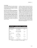
Table 2-29
External Functions Setpoint Range
The
initiating inputs are user-designated for each enabled external
function. The operation of any externally connected contact (across
these M-3425 inputs) will start the external function timer operation.
Each enabled external function requires a time delay setting.
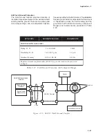
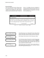
For the following example of the setup of an external function (see
Figure 2-21, External Function Example), the function is ENABLED.
The designated initiating contacts as described here are IN2 and
IN5. The designated blocking status input is IN3, and the designated
output contact for the function is OUT6.
A time delay setting is also required. The only logical limitation is
that the same status input cannot be both a designated initiating
input and a designated blocking input.
Summary of Contents for M-3425
Page 1: ...Instruction Book M 3425 Generator Protection ...
Page 14: ... 13 M 3425 Generator Protection Relay Figure 1 External Connections ...
Page 33: ...x M 3425 Instruction Book This Page Left Intentionally Blank ...
Page 89: ...M 3425 Instruction Book 2 52 This Page Left Intentionally Blank ...
Page 125: ...1 3 A B C M 3425 Instruction Book 4 26 This Page Left Intentionally Blank ...
Page 187: ...M 3425 Instruction Book 6 50 This Page Left Intentionally Blank ...
Page 207: ...M 3425 Instruction Book C 4 This Page Left Intentionally Blank ...
Page 209: ...D 2 M 3425 Instruction Book Figure D 1 Volts Hz 24 Inverse Curve Family 1 Inverse Square ...
Page 210: ...Inverse Time Curves Appendix D D 3 Figure D 2 Volts Hz 24 Inverse Family Curve 2 ...
Page 211: ...D 4 M 3425 Instruction Book Figure D 3 Volts Hz 24IT Inverse Curve Family 3 ...
Page 212: ...Inverse Time Curves Appendix D D 5 Figure D 4 Volts Hz 24IT Inverse Curve Family 4 ...
Page 215: ...D 8 M 3425 Instruction Book Figure D 5 Definite Time Overcurrent Curve ...
Page 216: ...Inverse Time Curves Appendix D D 9 Figure D 6 Inverse Time Overcurrent Curve ...
Page 217: ...D 10 M 3425 Instruction Book Figure D 7 Very Inverse Time Overcurrent Curve ...
Page 218: ...Inverse Time Curves Appendix D D 11 Figure D 8 Extremely Inverse Time Overcurrent Curve ...
Page 223: ...D 16 M 3425 Instruction Book This Page Intentionally Left Blank ...


