Operation – 3
3–3
Default Message Screens
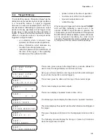
When powered up, the relay performs a number of
self-tests to ensure its correct operation. During the
self-tests, the display shows an “x” for each test
successfully executed. If all tests are executed
successfully, it will briefly display the word PASS
and then a series of status screens, including the
model number, the software version number, the
serial number, the date and time as set in the
system clock, and the user logo screen. If any test
should fail, an error code will be displayed and the
relay will not allow operation to proceed. In such a
case, the error code should be noted and the factory
contacted. A list of error codes and their descriptions
are provided in Appendix C, Error Codes.
When the relay is powered and unattended, user
logo lines are blanked.
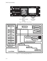
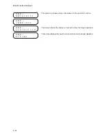
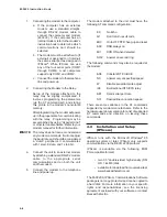
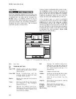
If a function has operated and the targets have not
been reset, the display will show the time and date
of the operation and automatically cycle through
screens for each applicable target (see Figure 3-2).
Pressing ENTER will begin local mode operation,
displaying the access code entry screen or, if access
codes have been disabled, the first level menu.
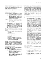
Figure 3-3 presents the main menu flow map for
HMI-equipped units. This map can be used as a
quick reference guide to aid in navigating the relay's
menus.
3.2
Initial Setup Procedure/
Settings
The M-3425 Generator Protection Relay is shipped
from the factory with all functions disabled (user will
only be able to enable purchased functions). The
following is a suggested setup procedure for initially
entering settings into the relay. While written for
HMI-equipped units, the same procedure applies
when setting the relay through remote
communication. Following the steps outlined below
are several sections which give additional detail
concerning the settings required for proper
commissioning.
Configuration Record forms are available in Appendix
A, Configuration Record Forms, to record settings
for future reference.
1.
Enter the Setup Unit data. This is general
information required including altering
access codes, setting date and time,
defining user logos, and other
adjustments. See Section 3.2, Setup
Unit Data subsection.
2.
Configure the Setup System data. This
is the general system and equipment
information required for operation,
including such items as CT and VT ratios,
VT configuration, and Nominal values.
See Section 3.2, Setup System Data
subsection.
3.
Enable the desired functions and
elements. See Section 3.2, Configure
Relay Data subsection.
4.
Enter the desired setpoints for the
enabled functions. See Section 3.2,
Setpoints and Time Settings subsection.
5.
Enter configuration information for the
oscillograph recorder. See Section 3.2,
Oscillograph Recorder Data subsection.
6.
If remote communication is used, set
the parameters as needed. See Section
3.2, Communications Data subsection,
or in Chapter 4, Remote Operation.
Setup Unit Data
To input the data, access the SETUP UNIT menu
as follows:
1.
Press ENTER to bring up the main menu.
2.
Press the right arrow button until SETUP
UNIT appears on the top line of the
display.
3.
Press ENTER to access the SETUP
UNIT menu and begin the data input.
The general information required to complete the
input data in this section includes:
Access Codes: The relay has three levels of access
codes. Depending on their assigned code, users
have varying levels of access to the installed
functions.
1.
Level 1 access = Read setpoints,
monitor status, view target history.
Summary of Contents for M-3425
Page 1: ...Instruction Book M 3425 Generator Protection ...
Page 14: ... 13 M 3425 Generator Protection Relay Figure 1 External Connections ...
Page 33: ...x M 3425 Instruction Book This Page Left Intentionally Blank ...
Page 89: ...M 3425 Instruction Book 2 52 This Page Left Intentionally Blank ...
Page 125: ...1 3 A B C M 3425 Instruction Book 4 26 This Page Left Intentionally Blank ...
Page 187: ...M 3425 Instruction Book 6 50 This Page Left Intentionally Blank ...
Page 207: ...M 3425 Instruction Book C 4 This Page Left Intentionally Blank ...
Page 209: ...D 2 M 3425 Instruction Book Figure D 1 Volts Hz 24 Inverse Curve Family 1 Inverse Square ...
Page 210: ...Inverse Time Curves Appendix D D 3 Figure D 2 Volts Hz 24 Inverse Family Curve 2 ...
Page 211: ...D 4 M 3425 Instruction Book Figure D 3 Volts Hz 24IT Inverse Curve Family 3 ...
Page 212: ...Inverse Time Curves Appendix D D 5 Figure D 4 Volts Hz 24IT Inverse Curve Family 4 ...
Page 215: ...D 8 M 3425 Instruction Book Figure D 5 Definite Time Overcurrent Curve ...
Page 216: ...Inverse Time Curves Appendix D D 9 Figure D 6 Inverse Time Overcurrent Curve ...
Page 217: ...D 10 M 3425 Instruction Book Figure D 7 Very Inverse Time Overcurrent Curve ...
Page 218: ...Inverse Time Curves Appendix D D 11 Figure D 8 Extremely Inverse Time Overcurrent Curve ...
Page 223: ...D 16 M 3425 Instruction Book This Page Intentionally Left Blank ...

