Operation – 3
3–7
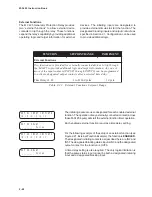
8 are form “c” contacts (center tapped “a” and “b”
contacts). Output contacts 1–4 contain special
circuitry for high-speed operation and pick up about
4
µ
sec faster than other contacts.
See Section 2.1, Configuration, for more information.
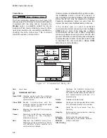
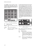
Setpoints and Time Settings
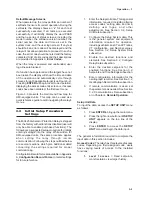
To input the data, access these menus as follows:
1.
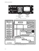
Press ENTER to bring up the main menu.
2.
Press the right arrow button until
VOLTAGE RELAY, the first of the
setpoint and time setting menus, appears
on the top line of the display.
■
NOTE: Some menus are dynamic, and do not
appear if the function is not purchased
or is unavailable.
3. Press ENTER to begin the data input for
this menu, or continue pressing the right
arrow button until the desired setpoint and
time setting menu appears, and then press
ENTER to begin the data input.
The general information required to complete the
input data in this section includes individual relay
function:
•
pickup settings (converted to relay
quantities)
•
time delay settings
•
frequency settings
•
time dials
•
power level settings (in percent rated)
•
impedance diameter in relay ohms for
distance and offset settings
Settings should be programmed based on system
analysis as described in Chapter 2, Application. A
complete description of the individual function as
well as guidelines for settings are explained therein.
Oscillograph Recorder Data
To input the data, access the OSCILLOGRAPH
RECORDER menu as follows:
1.
Press ENTER to bring up the main menu.
2.
Press the right arrow button until
OSCILLOGRAPH RECORDER appears
on the top line of the display.
3.
Press ENTER to access the
OSCILLOGRAPH RECORDER menu
and begin the data input.
The Oscillograph Recorder provides comprehensive
data recording (voltage, current, and status input/
output signals) for all monitored waveforms (at 16
samples per cycle). Oscillograph data can be
downloaded via the communications ports to any
IBM compatible personal computer running the
M-3820A IPScom
®
Communications software
package. Once downloaded, the waveform data
can be examined and printed using the optional
M-3801C IPSplot
®
Oscillograph Data Analysis
Software package.
The general information required to complete the
input data of this section includes:
•
Recorder Partitions: When untriggered,
the recorder continuously records
waveform data, keeping the data in a
buffer memory. The recorder's memory
may be partitioned into 1 record of 170
cycles, 2 records of 112 cycles, 3 records
of 84 cycles, or 4 records of 68 cycles
each. When triggered, the time stamp is
recorded, and the recorder continues
recording for a user-defined period. The
snapshot of the waveform is stored in
memory for later retrieval using IPScom
Communications Software. The OSC TRIG
LED on the front panel will indicate a
recorder operation (data is available for
downloading).
•
Trigger Inputs and Outputs: The recorder
can be triggered remotely through serial
communications via IPScom, or
automatically via programmed status
inputs (IN1–6) or outputs (OUT1–8).
•
Post-Trigger Delay: A post-trigger delay
of 5% to 95% must be specified. After
triggering, the recorder will continue to
store data for the programmed portion of
the total record before rearming for the
next record. For example, a setting of
80% will result in a record with 20%
pretrigger data, and 80% post-trigger data.
Communications Data
To input the data, access the COMMUNICATION
menu as follows:
1.
Press ENTER to bring up the main menu.
2.
Press the right arrow button until
COMMUNICATION appears on the top
line of the display.
3.
Press ENTER to access the
COMMUNICATION menu and begin the
data input.
Summary of Contents for M-3425
Page 1: ...Instruction Book M 3425 Generator Protection ...
Page 14: ... 13 M 3425 Generator Protection Relay Figure 1 External Connections ...
Page 33: ...x M 3425 Instruction Book This Page Left Intentionally Blank ...
Page 89: ...M 3425 Instruction Book 2 52 This Page Left Intentionally Blank ...
Page 125: ...1 3 A B C M 3425 Instruction Book 4 26 This Page Left Intentionally Blank ...
Page 187: ...M 3425 Instruction Book 6 50 This Page Left Intentionally Blank ...
Page 207: ...M 3425 Instruction Book C 4 This Page Left Intentionally Blank ...
Page 209: ...D 2 M 3425 Instruction Book Figure D 1 Volts Hz 24 Inverse Curve Family 1 Inverse Square ...
Page 210: ...Inverse Time Curves Appendix D D 3 Figure D 2 Volts Hz 24 Inverse Family Curve 2 ...
Page 211: ...D 4 M 3425 Instruction Book Figure D 3 Volts Hz 24IT Inverse Curve Family 3 ...
Page 212: ...Inverse Time Curves Appendix D D 5 Figure D 4 Volts Hz 24IT Inverse Curve Family 4 ...
Page 215: ...D 8 M 3425 Instruction Book Figure D 5 Definite Time Overcurrent Curve ...
Page 216: ...Inverse Time Curves Appendix D D 9 Figure D 6 Inverse Time Overcurrent Curve ...
Page 217: ...D 10 M 3425 Instruction Book Figure D 7 Very Inverse Time Overcurrent Curve ...
Page 218: ...Inverse Time Curves Appendix D D 11 Figure D 8 Extremely Inverse Time Overcurrent Curve ...
Page 223: ...D 16 M 3425 Instruction Book This Page Intentionally Left Blank ...


