2–7
Application - 2
2.4
Setpoints and Time Settings
21 Phase Distance
The phase distance function, designed for system
phase fault protection, is implemented as a two-
zone mho characteristic. Three separate distance
elements are implemented to detect AB, BC, and
CA fault types. The diameter, offset, system
impedance angle (relay characteristic angle), and
definite time delay need to be selected for each
zone for coordination with the system relaying in the
specific application.
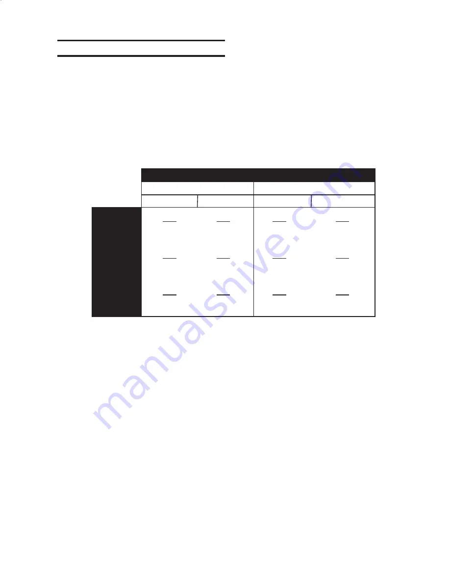
When the Dispersed Generation (DG) is connected
to the system through a delta/wye transformer,
proper voltages and currents (equivalent to the high
side of the transformer) must be used in order for
the relay to see correct impedances for system
faults. By enabling the delta/wye transform feature
(see Section 2.2,
System Diagrams
), the relay can
internally consider the 30° phase shift through the
delta-wye unit transformer, saving auxiliary VT costs.
Delta/Wye Transformer Connected
Direct-Connected
VT Connection
VT Connection
Line-to-Line
Line-to-Line
Line-to-Ground
Line-to-Ground
V
AB
I
a
-I
b
V
B
-V
0
I
b
V
C
-V
0
I
c
V
A
-V
0
I
a
V
BC
I
b
-I
c
V
CA
I
c
-I
a
V
C
-V
A
I
c
-I
a
V
B
-V
C
I
b
-I
c
V
A
-V
B
I
a
-I
b
V
CA
-V
BC
(3)I
c
V
AB
-V
CA
(3)I
a
V
BC
-V
AB
(3)I
b
AB Fault
BC Fault
CA Fault
Table 2-1
Impedance Calculation
Summary of Contents for M-3520
Page 1: ...Instruction Book M 3520 Intertie Protection Relay ...
Page 83: ...2 50 M 3520 Instruction Book This Page Left Intentionally Blank ...
Page 95: ...M 3520 Instruction Book 3 12 This Page Intentionally Left Blank ...
Page 133: ...M 3520 Instruction Book 5 12 This Page Intentionally Left Blank ...
Page 195: ...A 20 M 3520 Instruction Book This Page Intentionally Left Blank ...
Page 213: ...D 12 M 3520 Instruction Book This Page Intentionally Left Blank ...


