Bedrock SPS.500 Overview
Chapter 1
9/3/21
Bedrock SPS.500 User Manual - BRDOC125_007
5
communicate with a Bedrock SIO4.E communications module or UCG.5
gateway. Note that the “OR”ing Output connector must be used for redundant
configurations.
Figure 1
-
4 SPS.500 Redundant Configuration
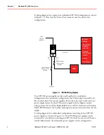
The SPS.500 can be placed in a parallel configuration with an UPS.500. A
parallel configuration will continue to power the load if either the SPS.500
power supply or the UPS.500 is no longer supplying power. The load must be
capable of accepting ORed inputs. Figure 1
-
5 shows a wiring diagram with the
Recommended
Fusing / Circuit
Breaker
Power
In
“OR”ed
Power Out
Recommended
Fusing / Circuit
Breaker
Relay
Output
(optional)
Et h er n et
AC Mains A
Load
Ethernet
Switch
(not needed with
SIO4.E, UCG.5, or
OSA Remote)
Power
In
“OR”ed
Power Out
Recommended
Fusing / Circuit
Breaker
Recommended
Fusing / Circuit
Breaker
AC Mains B
10/100
Et h er n et
10/100
Et h er n et
Relay
Output
(optional)
Workstation
Running OPC UA
or
SIO4.E, UCG.5, or OSA Remote


