Chapter 4
Configuration and Status
30
Bedrock SPS.500 User Manual - BRDOC125_007
9/3/21
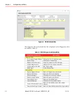
Figure 4
-
8 SPS.500 Network Data
The diagnostic data and network data that is displayed on the Diagnostics tab is
described in Table 4
-
5.
Table 4
-
5 SPS.500 Diagnostic and Network Data
Diagnostic Information
Description
Diagnostic Data
12 V Auxiliary Supply Voltage
Voltage from the 12 V auxiliary supply
Latched Flags
Three bytes of latched flags
Measured Input Frequency
Frequency measured on the SPS input
Output Voltage Control
Voltage on the 24 V output of the SPS
Output Voltage of the PFC
PFC output voltage
Status flags
16 bits of status flags
Network Data
Receive Alignment Errors
Number of alignment errors detected
Receive CRC Errors
Number of CRC errors detected
Receive Messages
Total number of all received packets
Receive Unicast Frames
Number of good unicast frames
Transmit Byte Count
Number of transmitted bytes
Transmit Messages
Total number of transmitted packets
Transmit After Multiple Collision Number of transmitted packets after multiple
collisions
Transmit After Single Collision Number of transmitted packets after a single collision


