SPS.500 Wiring
Chapter 3
9/3/21
Bedrock SPS.500 User Manual - BRDOC125_007
17
Cable Pin Out
Information
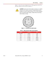
Cable pin out diagrams and tables are shown below. Note that the connector end
of each cable is shown in the figures.
2 shows the pin out diagram for the AC power in cable. Pin functions
and wire colors are shown in Table 3
Figure 3
-
2 AC Power In Cable Connector
3 shows the pin out diagram for the power out cable. Pin functions
and wire colors are shown in Table 3
NOTE:
Length of the Power Out cable should not exceed 9
meters (29.5 feet).
CAUTION:
Each contact in the output connectors is rated for
6 amps at 25°C. All wires must be connected to the load in
parallel. Do not use separate wires. Do not connect separate
wires to separate loads. Failure to follow these instructions
will void any warranty.
Table 3
-
1 AC Power In Cable Pin Out Information
Pin/Wire
Function
Color
Pin 1
LINE
BLACK
Pin 2
NEUTRAL
WHITE
Pin 3
GROUND
GREEN
Pin PE
Drain Wire
N/A


