


SAFETY INFORMATION
Even though the helloBEEprusa 3D printer was designed to be as safe as possible,
we would like to remind you it was conceived to be used by adults.
Still, there are safety concerns you must keep in mind:
Other information you need to know
After assembling your helloBEEprusa, don’t drop/knock/damage it and don’t connect it to anything
that hasn’t been previously validated by BEEVERYCREATIVE.
Make sure gases, explosive and other flammable materials aren’t kept, stored or transported
with your helloBEEprusa 3D printer or its parts.
ADULT SUPERVISION
COOL AND WELL-VENTILATED
ENVIRONMENT
MOVING PARTS
HIGH TEMPERATURES
For better results with helloBEEprusa,
it is recommended you maintain an acceptable level
of air quality around the printer.
Environments with some ventilation are also recommended
so as to renew the air if you choose to print
with materials that release odors.
Because we can’t stress this enough,
helloBEEprusa was developed to be used by adults.
Should you wish that children also use it,
you must supervise them at all times while they do so.
You must also take great care with small printed objects,
because children might try to swallow them,
which poses a danger of them choking.
Whenever helloBEEprusa is functioning,
some mechanical parts can reach high temperatures,
which can cause serious burns if touched.
For that reason you must always be careful
not to touch it.
Whenever it’s functioning,
helloBEEprusa has moving parts.
For that reason, you should always keep a safe distance
from the printer while it’s operating.
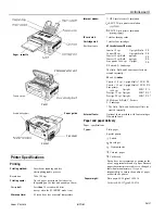
Summary of Contents for Hello BEE Prusa
Page 1: ...ASSEMBLY MANUAL ...
Page 2: ......
Page 3: ...V3 310815 ...
Page 10: ...A ASSEMBLING THE STRUCTURE ...
Page 11: ...A 1 STRUCTURE ...
Page 14: ...BUTTON HEAD SCREW DIN7380 M4X10 SERRATED LOCK WASHER DIN6798J M4 HEX THIN NUT 1 DIN439 M4 A 4 ...
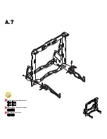
Page 17: ...BUTTON HEAD SCREW DIN7380 M4X10 SERRATED LOCK WASHER DIN6798J M4 HEX THIN NUT 1 DIN439 M4 A 7 ...
Page 22: ...B ASSEMBLING THE BUILD PLATE STRUCTURE ...
Page 26: ...B 4 END STOP LEVER X Y ...
Page 28: ...B 6 BUTTON HEAD SCREW DIN7380 M4X10 SERRATED LOCK WASHER DIN6798J M4 HEX THIN NUT 1 DIN439 M4 ...
Page 29: ...C ASSEMBLING THE EXTRUDER ...
Page 30: ...C 1 STRUCTURE ...
Page 38: ...C 9 END STOP LEVER X Y ...
Page 39: ...D ASSEMBLING THE X AXIS ...
Page 40: ...D 1 X SUPPORT HEX THIN NUT 2 D439 M5 LINEAR GUIDE 8X385MM X STRUCTURE ...
Page 43: ...D 4 X SUPPORT C EXTRUDER HEX THIN NUT 2 DIN439 M5 ...
Page 44: ...D 5 STRUCTURE ...
Page 47: ...D 8 CYL HEAD SCREW D912 M3X30 ADJUSTABLE Z END STOP ...
Page 48: ...E HOW THE 3 AXES AND ALL THEIR COMPONENTS COME TOGETHER ...
Page 50: ...E 2 LINEAR GUIDE 8X335MM Z Guides should slide freely ...
Page 51: ...E 3 After this step move the extruder to feel if it slides freely on both axies X and Z ...
Page 53: ...E 5 THREADED ROD DIN976 A2 M5X320 ...
Page 55: ...E 7 GT2 RUBBER BELT CABLE TIE 2 5X100MM Place to put the Cable Tie ...
Page 56: ...F ASSEMBLING THE ELECTRONICS ...