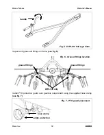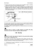
The tine arms are separated in two bundles (left and right). Separate the tine arms and
determine which are right and which are left. This is done by holding the tine arm with
the tine away from you. A right tine arm will have the tine bending to the right then
pointing straight down, while a left tine arm will have the bend going towards the left
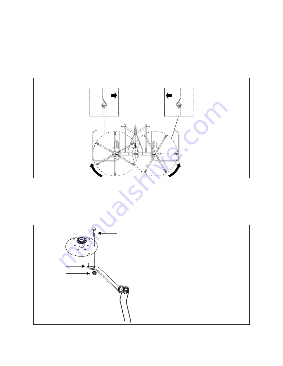
then down. Looking at the machine from the rear, place the right hand tine arms next to
the right rotor and the left hand tine arms next to the left rotor
(see fig. 8)
.
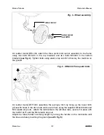
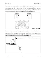
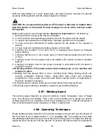
There are two adjustable tine arms per rotor with threaded holes and four fixed arms
with a welded pin on each arm. Install the four fixed tine arms using the M14x40 bolts
and the M14 elastic stop nuts. Place the welded pin at the end of the tine arm in the
inside hole on the bottom of the rotor flange. With a rubber mallet, hammer the tine arm
until it is flush against the bottom of the rotor flange
(see fig. 9)
.
O
PERATION
15
BEFCO
R
OTARY
T
EDDERS
O
PERATOR
’
S
M
ANUAL
Fig. 8 - Tine arms.
left tine
right tine
Fig. 9 - Tine arm assembly.
bolt M14x40
welded pin
nut M14
Summary of Contents for DR0-330
Page 36: ......
Page 40: ...ROTARY TEDDERS RIGHT FRAME OPERATOR S MANUAL DR0 330 DRP 330 PARTS MANUAL 40 BEFCO 01 2012...
Page 54: ......


