background image

TABLE 1 - TORQUE SPECIFICATIONS

When using lock washers with nuts, increase torque values by 5%.

3557

4823

2194

2974

978

1326

12

1-1/2”

2607

3535

1830

2482

1131

1534

4

M36

3161

4286

1949

2643

869

1179

6

1-1/2”

1659

2250

1180

1600

738

1000

2

M30

2712

3677

1673

2268

746

1011

12

1-3/8”

1499

2033

1047

1420

668

906

3.5

M30

2382

3230

1469

1992

655

888

6

1-3/8”

1176

1594

825

1119

530

719

2

M27

2012

2728

1241

1682

553

750

12

1-1/4”

1103

1496

774

1050

484

656

3

M27

1817

2463

1120

1519

500

677

7

1-1/4”

808

1095

567

769

360

488

2

M24

1445

1958

891

1208

397

539

12

1-1/8”

750

1017

526

714

327

444

3

M24

1288

1746

794

1077

354

480

7

1-1/8”

644

873

452

613

281

381

1.5

M22

995

1348

704

955

273

371

12

1”

595

807

418

567

254

344

2.5

M22

909

1232

644

873

250

339

8

1”

476

646

335

454

212

288

1.5

M20

668

906

473

642

184

249

14

7/8”

437

592

306

415

189

256

2.5

M20

606

822

430

582

167

226

9

7/8”

343

465

241

327

150

203

1.5

M18

420

569

297

403

192

261

16

3/4”

327

443

229

311

145

196

2

M18

376

509

266

361

172

233

10

3/4”

310

421

218

295

133

181

2.5

M18

240

325

170

230

110

149

18

5/8”

236

320

161

218

104

141

1.5

M16

212

287

150

203

97

132

11

5/8”

223

302

152

206

97

131

2

M16

171

232

121

164

79

106

18

9/16” 

154

209

105

142

69

94

1.5

M14

154

208

109

147

70

95

12

9/16” 

144

195

98

133

62

84

2

M14

120

163

85

115

55

75

20

1/2”

98

133

66

90

44

59

1.25

M12

106

144

75

102

48

66

13

1/2”

94

128

64

87

41

56

1.5

M12

78

106

55

75

36

48

20

7/16”

91

123

62

84

40

54

1.75

M12

70

95

49

67

32

43

14

7/16”

58

78

39

53

26

35

1

M10

49

67

35

47

23

31

24

3/8”

55

75

38

51

24

33

1.25

M10

44

59

31

42

20

27

16

3/8”

52

71

35

48

23

31

1.5

M10

27

37

19

26

13

17

24

5/16”

28

38

19

26

13

17

1

M8

25

33

17

24

11

15

18

5/16”

27

36

18

25

12

16

1.25

M8

14

19

10

13

6

8

28

1/4”

11

15

7

10

4

6

1

M6

12

16

8

11

5

7

20

1/4”

7

9

4

6

3

4

0.8

M5

ft-lb

N.m

ft-lb

N.m

ft-lb

N.m

Thread

inch

tpi

Bolt
size

inch

ft-lb

N.m

ft-lb

N.m

ft-lb

N.m

Thread

mm

Bolt
size

mm

Grade 8

Grade 5

Grade 2

Inch (SAE)
treaded
bolts head
marking

Class 10.9

Class 8.8

Class 5.8

Metric (ISO)
treaded
bolts head
marking

TABLE 2 - ROTARY TEDDERS - TECHNICAL FEATURES

ASAE 2

nd.

 cat.

6

2

457

11”

Pull type

20-50

DRP-330

ASAE 2

nd.

 cat.

6

2

441

11”

Three point

20-50

DR0-330

Driveline w/ratchet torque

limiter 1

 3

/

8

# of Tines

per rotor

# of Rotors

Weight lb.

Working

width

Hitch type

HP

Model

Series DR0-330 & DRP-330, for tractors up to 50 HP, PTO 540 rpm

M

AINTENANCE

29

BEFCO

R

OTARY

 T

EDDERS

O

PERATOR

S

 M

ANUAL

Summary of Contents for DR0-330

Page 1: ...BEFCO Operator s Manual HAY EQUIPMENT Rotary Tedders DR0 330 DRP 330 The operator s manual is a technical service guide and must always accompany the machine Manual 960 390B February 2015...

Page 2: ...r each have been selected using the following guidelines DANGER Indicates an imminently hazardous situation that if not avoided will result in death or serious injury WARNING Indicates a potentially h...

Page 3: ...ansportation 22 3 10 Removing Tedder from the Tractor 21 3 09 Uneven Terrain 19 3 08 Operating Techniques 19 3 07 Working Speed 18 3 06 Start Up 17 3 05 Attaching to the Tractor 16 3 04 Pre Operationa...

Page 4: ...perator CAUTION Unless otherwise specified all hardware is metric Use only metric tools on metric hardware Other tools that do not fit properly can slip and cause injury CAUTION Right hand and left ha...

Page 5: ...ty covers defective material and workmanship The cost of normal maintenance or repairs for accidents or improper use and related labor will be borne by the owner 1 03 Model and Serial Number ID Attach...

Page 6: ...n that the operator prior to operating reads and understands the operator s manuals and is instructed in safe and proper use 2 01 Preparation 1 Before operating equipment read and understand the opera...

Page 7: ...until tines have come to a complete stop 8 To park the vehicle safely stop vehicle on a level surface not on a slope disengage PTO engage the parking brake stop the engine remove the key and wait for...

Page 8: ...Fig 2 Safety decals implement replace immediately if damaged SAFETY PRECAUTIONS 8 BEFCO ROTARY TEDDERS OPERATOR S MANUAL right side left side...

Page 9: ...Safety decals driveline replace immediately if damaged SAFETY PRECAUTIONS 9 BEFCO ROTARY TEDDERS OPERATOR S MANUAL placed on outer shield placed on outer tube...

Page 10: ...are very much due to the responsible use of the equipment It must always be operated prudently following with great care the safety instructions laid out in this manual 1 The use of this equipment is...

Page 11: ...and roots in the terrain and other hidden hazards Keep away from drop offs 17 Use extreme care and maintain minimum ground speed when transporting on hillside over rough ground and when operating clos...

Page 12: ...LW2 2 2 Wheel 15x600 6 6 6 Right tine arms with attached tines 6 6 Left tine arms with attached tines 1 Pull type drawbar assembly 1 Three point hitch carrier assembly 1 1 Main frame with gearbox and...

Page 13: ...up the lower hitch yokes with holes in the drive tube and secure them using the supplied M14x90 bolts and M14 elastic stop nuts Attach the turnbuckle to the left drive tube secure it in place with the...

Page 14: ...gearbox output shaft using the supplied hose clamp see fig 7 OPERATION 14 BEFCO ROTARY TEDDERS OPERATOR S MANUAL Fig 5 DRP 330 Pull type hitch 1 handle Fig 6 Grease fittings location grease fittings...

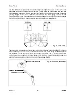
Page 15: ...the right rotor and the left hand tine arms next to the left rotor see fig 8 There are two adjustable tine arms per rotor with threaded holes and four fixed arms with a welded pin on each arm Install...

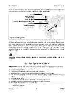
Page 16: ...TION Always keep safety guards in extended position while unit is in operation 3 04 Pre Operational Check IMPORTANT Check each of the following carefully prior to engaging the equipment 1 The rotor be...

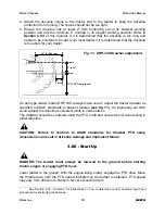
Page 17: ...essure is correct It is important to strictly follow the safety guidelines and instructions laid out in the tractor s operator s manual To attach the tedder to the tractor do the following 1 On tedder...

Page 18: ...riveline s universal joints to undue stress The drawbar should be centered under the PTO shaft and secured so it cannot swing in either direction CAUTION Failure to conform to ASAE standards for drawb...

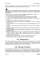
Page 19: ...with the tractor s operator s manual 10 Checking that the PTO shield and all other shielding are on the machine and securely in place 11 Making sure the proper attire is worn Avoiding loose fitting cl...

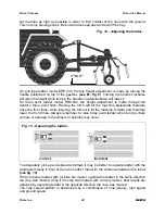
Page 20: ...e machine forward and therefore lower the front tines Always remember to raise three point tedder when turning sharp corners or damage to the wheels or spindles may occur To adequately pick up and spr...

Page 21: ...operating unit Enter new areas carefully CAUTION For emergency reasons learn how to stop the tractor and tedder quickly On the tedder always disengage the PTO lock parking brake stop engine and allow...

Page 22: ...ar and carefully drive tractor away from tedder 1 Park tedder on level and solid ground 2 Disengage the tractor s PTO and make sure all parts have come to a complete stop 3 Set parking brake and place...

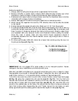
Page 23: ...ctor drawbar Leave only enough slack in chain to permit turning 8 On three point tedder DR0 330 block the wheels from pivoting using the lever on the wheel shaft see 1 fig 15 IMPORTANT Do not engage P...

Page 24: ...to raise the unit see fig 18 Slowly raise the unit to make sure the weight is balanced correctly OPERATION 24 BEFCO ROTARY TEDDERS OPERATOR S MANUAL Fig 16 Folding tine arms 1 2 1 tine arm wrench 2 s...

Page 25: ...ment have come to a complete stop before attempting to perform maintenance 6 Never work under equipment unless it is blocked securely 7 Always use personal protection devices such as eye hand and hear...

Page 26: ...Hourly or whenever an obstacle is hit 1 Check the conditions of the tines joints rotors and gearboxes Every 8 hours 1 Lubricate driveline Apply two or three shots of grease to the driveline cross and...

Page 27: ...le tube guard leaving a 1 gap between the end of the guard tube and bell guard 3 Cut off both guard tubes the same amount as marked in step 2 4 Shorten both drive tubes the same amount as guard tubes...

Page 28: ...line that comes equipped with a ratchet torque limiter The PTO yoke end is attached to the tractor s PTO while the end with the ratchet torque limiter is attached to the tedder The purpose of the limi...

Page 29: ...2 287 150 203 97 132 11 5 8 223 302 152 206 97 131 2 M16 171 232 121 164 79 106 18 9 16 154 209 105 142 69 94 1 5 M14 154 208 109 147 70 95 12 9 16 144 195 98 133 62 84 2 M14 120 163 85 115 55 75 20 1...

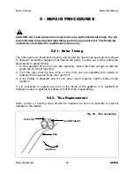
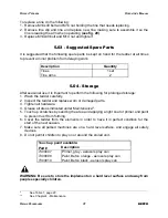
Page 30: ...djusting loosen the bolts enough so that the gears are no longer meshing 2 Turn the rotor until the tine arms on the rotor you are adjusting turn exactly in between the tine arms of the rotor next to...

Page 31: ...n or damaged parts 3 Tighten all hardware 4 Grease all areas indicated under Maintenance10 5 Touch up scratches by sanding the area and applying a light coat of primer and paint to prevent rust from f...

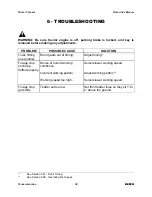
Page 32: ...lect slower working speed Adjust working pattern12 Select slower working speed Dense or humid working conditions Incorrect working pattern Working speed too high Forage crop not being fluffed properly...

Page 33: ...ng of bearings Operator s Manual Review the Operator s Manual with the customer Explain the following Warranty Safe operation and service Correct machine installation and operation Daily and periodic...

Page 34: ...or performance of any warranty on the Company s Machine are those set forth herein In no event will the dealer the Company or any company affiliated with the Company be liable for a Injuries or damage...

Page 35: ...hop It is assumed that the dealer has the appropriate general and special tools to service the Machine Time required for replacement of knives oil grease and to remove excessive dirt from the Machine...

Page 36: ......

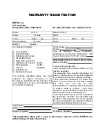
Page 37: ...and understand clearly that there were and are no other representations of warranties either expressed or implied made by anyone I have been advised on proper operation maintenance and lubrication pr...

Page 38: ...Cut along this line Sender Fold here BEFCO Inc Warranty Department P O Box 6036 Rocky Mount NC 27802 6036 Place stamp here...

Page 39: ...BEFCO Parts Manual HAY EQUIPMENT Rotary Tedders DR0 330 DRP 330 Parts Manual 02 2015 DR0 330 DRP 330 BEFCO DR0 330 DRP 330 US lwp Printed on February 23 2015...

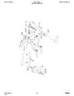
Page 40: ...ROTARY TEDDERS RIGHT FRAME OPERATOR S MANUAL DR0 330 DRP 330 PARTS MANUAL 40 BEFCO 01 2012...

Page 41: ...mplete wheel 15x600 6 502 375B 32 2 Bearing 6205 ZZ 000 6626A 30 1 Outer cover 502 374B 29 1 Inner cover 502 373B 28 1 Washer 30x60x5 502 364B 26 1 Bearing 30206 005 8472 25 6 Bolt HH M14 2 00x40 C8 8...

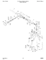
Page 42: ...ROTARY TEDDERS LEFT FRAME AND CENTRAL GEARBOX OPERATOR S MANUAL DR0 330 DRP 330 PARTS MANUAL 42 BEFCO 08 2014...

Page 43: ...72 25 6 Bolt HH M14 2 00x40 C8 8 Z F 007 4232 24 1 Flange with gear 502 976B 23 1 Bearing 6206 004 1422 22 1 Spacer 30x42x21 502 360B 21 1 Lower oil plug 502 974B 20 6 Lock washer 10 internal 501 861B...

Page 44: ...ROTARY TEDDERS LEFT FRAME AND CENTRAL GEARBOX OPERATOR S MANUAL DR0 330 DRP 330 PARTS MANUAL 44 BEFCO 08 2014...

Page 45: ...1 Bearing 6208 001 2149 58 2 Bolt SH M14 2 00x25 C8 8 Z F adjustable tine 502 977B 4 Bolt HH M14 2 00x40 C8 8 Z F fixed tine 007 4232 57 2 Key 8x7x30 000 6689 54 Qty Description Part Ref ROTARY TEDDE...

Page 46: ...1 Pull type tongue 503 003B 8 1 Bolt HH M16 2 00x70 C8 8 Z F 003 0309 7 1 Threaded rod 503 523B 6 1 Nut ES M16 2 00 Z TN 004 1165 5 1 Adjustment tube 503 623B 4 1 Pivot 503 521B 3 1 Handle plate 503 5...

Page 47: ...0 C8 8 Z P 000 5536 6 1 Washer flat 24 Z 002 9440 5 1 Nut ES M22 1 50 Z TK 002 9270 4 1 Adjustment tube 3000211D 3 1 Handle 3000202D 2 1 Pull type tongue 3000252D 1 Qty Description Part Ref ROTARY TED...

Page 48: ...int hitch 502 996B 5 1 Tine arm wrench 502 995B 4 2 Bolt HH M14 2 00x60 C8 8 Z P 003 0277 3 4 Nut ES M14 2 00 Z TN 001 5218 2 2 Bolt HH M14 2 00x30 C8 8 Z F 003 2618 1 Qty Description Part Ref ROTARY...

Page 49: ...x25 8900405D 5 2 Washer flat 12 000 2265 4 2 Nut ES M12 1 75 Z TK 001 3345 3 2 U bolt 502 999B 2 1 Safety guard right 503 568B 1 Qty Description Part Ref ROTARY TEDDERS SAFETY GUARDS OPERATOR S MANUAL...

Page 50: ...C8 8 Z F 003 0054 27 4 Washer flat 12 000 2265 26 2 Support bracket safety guard 3000320D 25 2 Safety guard 502 998B 24 2 Nut PT M12 1 75 C6 Z 003 0064 23 Qty Description Part Ref ROTARY TEDDERS SAFET...

Page 51: ...0040D 5 4 Bolt HH M12 1 75x50 C8 8 Z F 003 0054 4 2 Support bracket safety guard 3000320D 3 4 Plastic cap 25x25 8900405D 2 2 Safety guard 8800005D 1 Qty Description Part Ref ROTARY TEDDERS SAFETY GUAR...

Page 52: ...3 1 Support left safety guard 8800386D 1 Support right safety guard 8800385D 2 2 Safety guard 8800390D 1 Qty Description Part Ref ROTARY TEDDERS SAFETY GUARDS OPERATOR S MANUAL DR0 330 DRP 330 PARTS M...

Page 53: ...2130 38 2 Chain anti rotation 1006065C 37 1 Ratchet torque limiter LW2x02 1622250C 30 1 Yoke inner tube B2 1702029C 21 1 Roll pin 8x50 000 011E 14 1 Inner tube B2 29x4 1522108C 13 1 Outer tube B2 36x3...

Page 54: ......

Page 55: ...tails in this manual without the expressed written permission of the Company Technical information provided in this manual is approximate the Company reserves the right to modify or improve the models...

Page 56: ...BEFCO DR0 330 DRP 330 US lwp Printed in the USA February 23 2015 P O Box 6036 Rocky Mount NC 27802 6036 Tel 252 977 9920 Fax 252 977 9718 www befco com...

Reviews: