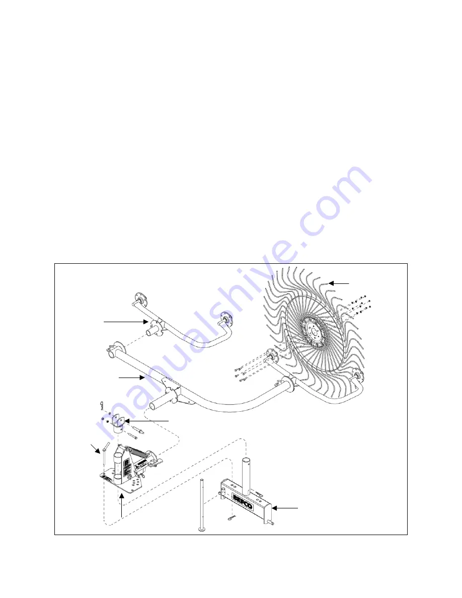
6. Slide the support arm of the rake into the large hole in the pivot housing of the frame
holder hitch until the flanges on both pieces are bumped up to one another. Secure
the support arm with the locking lever then secure the lever with the Ø12x56 locking
pin and the Ø3 hairpin cotter.
7. Slide each arm with hubs in the holes at each end of the support arm until the
flanges on both pieces are bumped up to one another. Secure the arm with the
locking lever then secure the lever with the Ø12x56 locking pin and the Ø3 hairpin
cotter. On hay rake models RS2-05 only, assemble the single wheel arm with hub in
the center hole of the support arm and secure it using the M14x100 bolt, the lock
washer and the M14 nut.
Note: When installing the arms with hubs always make sure to assemble them to the
support arm with the bend facing upwards. This will allow for better clearance from
the ground and therefore more hay to be raked.
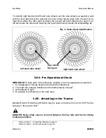
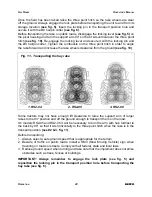
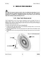
8. Assemble the wheels making sure the inner wheel is facing away from the tractor
(see fig. 4)
.
9. Secure each wheel by inserting the supplied M10x25 bolts on the hub side and the
Ø10 external lock washers and M10 nuts on the inner wheel side.
10. Assemble the foot stand on the base and secure it with the Ø4 hairpin cotter.
11. Tighten all hardware securely.
O
PERATION
12
BEFCO
H
AY
R
AKES
O
PERATOR
’
S
M
ANUAL
Fig. 3 - Rake assembly
frame holder hitch
top link support
support arm
three point hitch base
arm with
hubs
rake wheel
locking
pin
Summary of Contents for RS2-04L
Page 36: ...HAY RAKES FRAME OPERATOR S MANUAL RS2 04 PARTS MANUAL 36 BEFCO 08 2013...
Page 38: ...HAY RAKES FRAME OPERATOR S MANUAL RS2 05 PARTS MANUAL 38 BEFCO 08 2013...
Page 40: ...HAY RAKES FRAME OPERATOR S MANUAL RS2 06 PARTS MANUAL 40 BEFCO 12 2013...
Page 44: ...HAY RAKES DECALS OPERATOR S MANUAL RS2 04 RS2 05 RS2 06 PARTS MANUAL 44 BEFCO 08 2013...
Page 46: ......


