7.
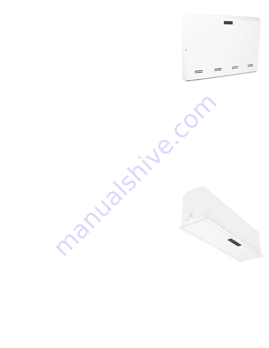
104.5 Recessed Mount (-R) Models:
1)
Remove cover and any packing material inside unit housing
that may have been used for shipping purposes.
2)
For ease of installation, and to prevent possible damage to
the equipment, the inverter/charger assembly may be tempo-
rarily removed prior to knockout removal and attachment to
mounting surface. This is accomplished by removing (4) 8-32
hex nuts on the inverter/charger mounting plate. If shipped
factory installed, batteries may also be temporarily removed to
facilitate ease of installation.
3)
Remove the appropriate knockouts, 7/8” diameter, on the top
and/or left side of the unit housing to facilitate conduit attachment. Also remove the appropriate
round knockouts, 5/16” diameter, which are located on all sides of unit housing. Specific knockout
requirements are dictated by mounting orientation of unit (vertical or horizontal) and location of
wall studs and /or other support members.
4)
Secure housing to support members through round knockouts using mounting hardware (not sup-
plied) sized appropriately to support the unit weight.
IMPORTANT: Unit should be so positioned that the cabinet extends between 3/8” and 3/4”
beyond the finished wall surface after installation.
5)
Prior to final attachment of unit cover, the LED indicator panel assembly position must be adjusted
to sit flush against inside surface of cover after attachment. This is accomplished using the (2)
8-32 hex nuts on the indicator assembly.
6)
Re-install inverter/charger assembly if removed in step 2.
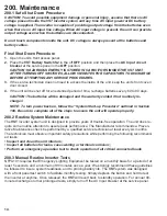
104.6 Ceiling T-Grid Mount (-T) Models:
1)
Remove cover and any packing material inside unit housing
that may have been used for shipping purposes.
2)
For ease of installation, and to prevent possible damage to
the equipment, the inverter/charger assembly may be tempo-
rarily removed prior to knockout removal and attachment to
mounting surface. This is accomplished by removing (4) 8-32
hex nuts on the inverter/charger mounting plate. If shipped
factory installed, batteries may also be temporarily removed
to facilitate ease of installation.
3)
Remove the appropriate knockout(s), 7/8” diameter, located
on either side of unit housing to facilitate conduit attachment.
IMPORTANT: Take care to remove only the knockouts required for utility connection. Re-
moval of knockouts if unused and left open will void the plenum rating of the unit.
4)
Mount the unit securely in place between T-Grid members.
NOTICE: Safety chain or cable, rated 50lb minimum working load, 250lb minimum breaking
strength is required to hang the unit in a T-Grid system. Failure to correctly install unit will
cause an unsafe condition!
5)
Re-install inverter/charger assembly if removed in step 2.


