13
860
76
D
B
-en/
03
35
5.0
00
32
English
⋅
en
Display and operating elements
EMERGENCY STOP button
Fig. 2
EMERGENCY STOP button on the left side
Key switch
Fig. 3
Key switch on the right side
Main switch
Fig. 4
Main switch on the rear side
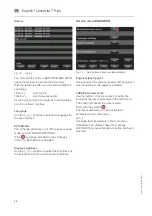
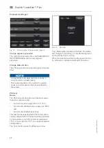
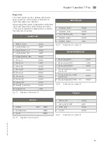
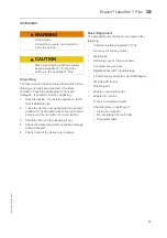
Key switch LASER EIN / AUS - ON / OFF
0
Off position: the key switch should be
in this position prior to turn on the
main switch.
1
Processor boots up, software is
started.
START
Lamp power supply is switched on,
laser flash lamp is ignited.
Opposite to the switch positions 0
and 1 the Start position is a
momentary position (the key switch
does not remain in this position).


