29
860
76
D
B
-en/
03
35
5.0
00
32
English
⋅
en
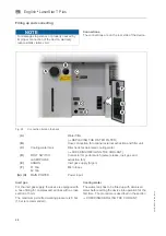
First putting into operation
After properly having finished all activities described
in the section
→
FILLING UP AND CONNECTING
switch on the device as explained in the section
TURNING ON THE UNIT.
If the self-test has been finished without an error
message, the device is ready for operation.
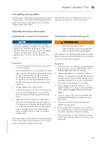
Adjusting the stereo microscope
Adjusting the crosshair and focal plane
Procedure:
1.
Turn on the system (only turn the main switch
to the "I" position).
2.
Put a sample item (e. g. a steel plate) on a lab
jack in the visual field of the stereo microscope
so that it appears sharp (together with the
crosshair) seen through the right eyepiece.
If necessary, turn the right adjustment ring so
that the item appears sharp through the right
eyepiece.
3.
Fix the sample item in this position.
4.
Look with the left eye through the left eye piece
and turn the left adjustment ring so that the
item also appears sharp through the left eye-
piece.
5.
Adjust the distance of the two eyepieces so
that both visual fields (that appear bright) of
both eyepieces completely overlap each other,
i. e. while observing the test item with relaxed
eyes one single round visual field appears
without a black border on either its inside or
outside edge.
After this setting, the test object must appear equally
sharp in the right and left eyepiece, and the cross-
hairs must also be sharply discernable.
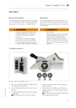
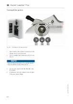
Centering the crosshair/welding point
If the position of the welding point on the workpiece
does not correspond to the position of the crosshair,
you have to adjust the crosshairs.
Procedure:
1.
Ensure that the microscope is adjusted ideally
for your eyes (
→
section ADJUSTING THE
CROSSHAIR AND FOCAL PLANE).
2.
Place a steel plate on a workpiece holder (a
lab jack, for example), and adjust the height of
the steel part so that its surface appears in the
sharpest possible focus (by turning the adjus-
ting screw on the lab jack, for example).
3.
Set a voltage of approximately 215 V at a
pulse duration of 1.2 ms (
→
section SETTING
THE LASER PARAMETERS IN THE MAIN
MENU).
4.
Look for a free surface on the steel part,
do
not touch it anymore
, and trigger a single
laser pulse.
5.
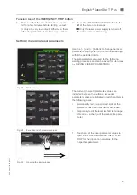
Check the positions of the welding point
(SPOT) and crosshair.
6.
If the crosshair is not exactly in the center of
the welding point, you have to adjust the posi-
tion of the crosshair. Proceed as follows:
7.
Use an Allen key (3 mm) to loosen the screw
under the microscope until the microscope can
be moved.
NOTE
To achieve precise and reproducible welding
results it is necessary to adjust the stereo micro-
scope to the individual visual acuity of the
operator. If the stereo microscope is not adjusted
correctly the workpiece can be recognized
exactly even if it is not in the focal plane of the
laser.
WARNING
Risk of burning your fingers!
If the crosshair is not properly adjusted
there is a risk of burning your fingers.


