background image

53

860

76

 D

B

-en/

03

 35

5.0

00

32

English 

⋅ 

LaserStar T Plus

en

Status and error messages/
Fault clearance

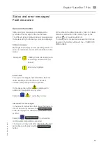
General information

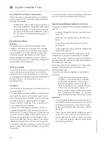
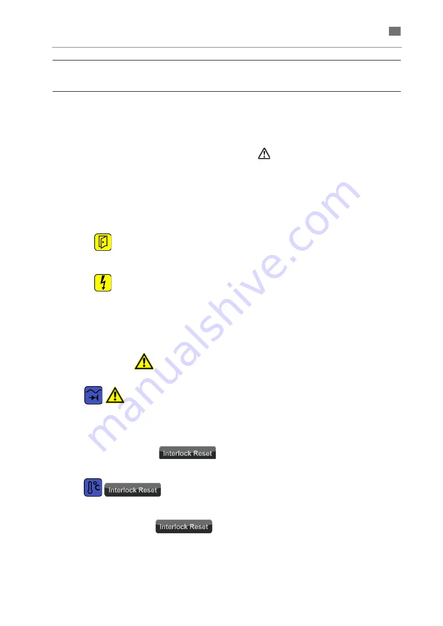
Status and error messages are displayed as 
symbols at the top edge of the touchscreen.
The different types of status and error messages are 
characterized by the following colors and displays.

Status messages

Messages that display normal operating states are 
show as individual symbols without additional infor-
mation.

Error notes

This type of messages indicates states that may 
cause subsequent malfunctions. The laser, 
however, temporarily remains operable. 

In this cases the symbol 

 is displayed in 

addition to the specific error symbol. 

Example:


 = water flow too low.

Interlock error messages

In the case of malfunctions that cause the device to 
turn off for security reasons, the 


button is displayed in addition to the specific error 
symbol.

Example:


 = permissible 

cooling water temperature exceeded.
The device will only work after eliminating the fault 
and subsequently pressing the 


button.

In the table in the following section, this error classi-
fication is referred to in the column Type by the 
symbol 

 or the abbreviation IL.

The arising error measures are saved and can be 
viewed in the History window of the --> SERVICE 
MENU USER.

Examples:

= Safety circuit interrupted (such 
as working chamber door not 
closed)

lamp not yet ignited.

Summary of Contents for LaserStar T Plus

Page 1: ...Gerätedokumentation Miteinander zum Erfolg ...

Page 2: ...LaserStar T Plus DOC 86076 en 03 English 355 00032 en ...

Page 3: ...86076 DB en 03 355 00032 ...

Page 4: ...Translation of the original instructions LASERSTAR T PLUS English 355 00032 en ...

Page 5: ... use in dental laboratories and comparable establish ments for research commercial and training purposes The unit must only be operated by dental professionals or they must provide supervision if trainees or other persons operate unit The operating instructions must be read and understood before the device is used This par ticularly applies to the Safety information The warranty is void in cases o...

Page 6: ...ing in the operating instructions We welcome any suggestions or criticism Please feel free to notify us Your effort will help us make the operating instructions more user friendly and respond more effectively to your wishes and needs Target group This document is directed toward everyone who works with this device or performs service tasks that are described in this document Contact information BE...

Page 7: ... not followed properly CAUTION This reference identifies only those hazards that are potential damaging to property and the environment NOTE This symbol identifies user tips and particularly useful information It helps you optimally exploit all the functions of your machine 1 Sequential actions are described in sequentially numbered paragraphs In most cases the operator s actions generate some kin...

Page 8: ... heed the information in this manual concerning the transport storage installation putting into operation operation and service and maintenance of this device Unauthorized structural modifications to this device Inadequate monitoring checking of parts of the device that are subject to wear Improperly performed repairs Catastrophes caused by alien elements or force majeure Exclusion of liability in...

Page 9: ...nyone transporting setting up operating servicing and repairing the LaserStar T Plus must be instructed and understand the potential dangers Carefully read understand and observe the operating instructions and especially the safety instructions A lack of or insufficient knowledge of the operating instructions negates all claims of liability against the company BEGO Bremer Goldschlägerei Wilh Herbs...

Page 10: ...removed or bridged The danger otherwise exists that an uncontrolled laser beam will cause serious eye damage or skin burns Personal protective equipment While properly using the machine the eyes are protected against damaging effects of the laser beam and against the UV radiation arising in the welding plasma and hazardous to the eyes while observing the welding process section DANGER FROM THE LAS...

Page 11: ...ds caused by faulty operation during proper use and to maintenance work on the laser Danger to hands In normal operation operators can accidentally pass their hand in front of the pulsing laser beam In this case the operator would receive a restricted burn on his hand or finger section WHAT TO DO IF YOU RECEIVE A BURN Eye protection As far as eye protection is concerned this device fulfills the re...

Page 12: ...le circumstances Be calm and concentrate when triggering laser pulses For subsequent pulses always use the micros cope to check that the workpiece is positioned correctly What to do if you receive a bum If you suspect that you have been burned your eyes immediately notify the laser safety supervisor or the safety expert and consult a doctor if necessary If you receive a burn from a laser pulse on ...

Page 13: ...ser head may only be done by autho rized service technicians who meet the following qualifications precise understanding of accident prevention regulation BGV A2 Electrical systems and equipment and accident prevention regulation BGV B2 Laser beam or equivalent national or international regulations e g EC Directive 60825 or IEC Publication 825 precise understanding of device specific func tions an...

Page 14: ...ystem when closed The individual function elements are identified by capital letters and defined below A Touch screen B Stereo microscope C Observation window with laser protective glass D Working chamber door E Hand openings F Pedal switch for triggering laser pulses and controlling inert gas and exhauster G Working chamber H Removable cover I Key switch ...

Page 15: ... V 60 Hz 13 A 1 phase Energy consumption max 230 V Standby ECO Modus 1 7 kW 0 2 kW 0 01 kW Laser data Laser crystal Nd YAG Wavelength 1 06 μm Power 60 W Pulse peak power 8 kW Pulse energy 60 J Pulse frequency Single pulse 1 50 Hz Focal diameter 0 2 2 6 mm Laser class closed Laser class open 4 document of compliance included 4 Elektromagnetic compatibility EMC The device meets the requirements of t...

Page 16: ...n switch Fig 4 Main switch on the rear side Key switch LASER EIN AUS ON OFF 0 Off position the key switch should be in this position prior to turn on the main switch 1 Processor boots up software is started START Lamp power supply is switched on laser flash lamp is ignited Opposite to the switch positions 0 and 1 the Start position is a momentary position the key switch does not remain in this pos...

Page 17: ...the configu ration and setting of the device for switching the exhauster and the inertgas The footswitch is connected to the system with flexible cable and can be moved into any position comfortable for the operator The footswitch is equipped with a strap to easily draw the footswitch towards the user NOTE When touching small symbols such as using the keyboard of the ALPHANUMERIC INPUT WINDOW it i...

Page 18: ...ion The status of the laser shutter is displayed on the touch screen SHUTTER STATUS DISPLAY It is influenced by the status of the working chamber door The laser shutter can only be opened when the working chamber door is closed and there is no disturbance in the power supply or the cooling circuit Descriptions of the menus Main menu Fig 7 Main menu After the system is turned on the MAIN MENU is di...

Page 19: ...e cooling water circuit Green normal operating temperature Orange increased operating temperature Red static max operating temperature reached Red static max operating temperature exceeded risk of shutdown Laser parameter area Display and setting of the laser parameters details SETTING THE LASER PARAMETERS IN THE MAIN MENU Touch these buttons to load the laser parameters stored under the previous ...

Page 20: ...be opened The laser shutter is enabled but closed because the safety circuit is open e g the working chamber door is open The laser is ready to emit laser pulses i e the laser shutter has been enabled and is open After a technical malfunction the device is blocked Once the malfunction has been eliminated it must be acknowledged with this touch button Press the Shutter button in the working chamber...

Page 21: ...ck to the input of lower case characters Button This button closes the input window the entered values or texts are taken to the higher level window Service menus The service menus are divided into four levels with different access rights General instructions concerning the ser vice menus The following buttons are generally available in the service menus User Each user without restriction no passw...

Page 22: ...nance recommendation is complied with without any of the above mentioned actions have occured The indicated values represent the percentage for the respective events in relation to the defined thres holds for details see the following description The Get button of the Sysinfo window opens the following window Fig 11 Maintenance recommendation Extraction filter degeneration This feature is not used...

Page 23: ...ed in the Change button the ECO Modus is disabled Display brightness Use the buttons to adjust the brightness of the touchscreen to the environmental conditions Service menu ENGINEER Fig 13 Service Menü Engineer Ebene Seite 1 Engineer level page 1 Having entered the engineer password the engineer level consisting of two pages is indicated LASER parameter lock Use the button in this line to lock or...

Page 24: ...eshold for the maintenance recommen dation for a lamp replacement Change water filter The Set button opens the ALPHANUMERIC INPUT WINDOW in order to confirm the replacement of the water filter It is recommended to confirm the replacement otherwise the system generates repeatedly inappro priate maintenance recommendations If you confirm the replacement of the water filter without having replaced it...

Page 25: ...led laser lamp This test has been performed at the factory with a supply voltage of 230 V The test must be performed by the customer only if the system is operated at 110 V The version for 110 V is an optional system configuration The Set button opens the following window Fig 16 PSU test The Start button initiates a PSU test The button text changes to Working on inverted background as long as the ...

Page 26: ... page 5 5 SAFETY I O 1 EMYC_CNC HIGH 2 Light_barrier_L1 LOW 3 Light_barrier_L2 HIGH 4 Light_barrier_R1 LOW 5 Light_barrier_R2 HIGH 6 Door_L1 HIGH 7 Door_L2 LOW 8 Door_R1 HIGH 9 Door_R2 HIGH 10 Hand_L1 HIGH 11 Hand_L2 HIGH 12 Hand_R1 HIGH 13 Hand_R2 HIGH 14 Safety_Customer HIGH 15 Fatal_Error LOW HEX I O 1 FLOW 208 HIGH 2 Temperature HIGH 3 Level HIGH SHUTTER I O 1 Shutter1_Error HIGH 2 Shutter1_Er...

Page 27: ...mbient conditions Temperature Humidity Max 85 rel non condensing Altitude Max 2500 mNN Connecting load The device can be used with the following electrical connection values 230 V 50 Hz 13 A single phase 110 V 60 Hz 16 A single phase DANGER When choosing the installation site take into consideration that for servicing a suitable limitation of the laser area is possible see the regula tions about a...

Page 28: ...for possible damage during transport 5 Check to see if the delivery is complete Basic Equipment The standard parts of delivery are listed in the following Complete welding Laserstar T Plus Two keys for the key switch Microscope Retaining ring for the microscope 3 m protective gas hose Digital pedal switch double stage 2 Power supply cable EU and USA Japan Fill tube with funnel Adjusting aid Adapte...

Page 29: ...26 86076 DB en 03 355 00032 English LaserStar T Plus en Mounting the stereo microscope Fig 22 Mounting the stereo mikroscope Part1 ...

Page 30: ...27 86076 DB en 03 355 00032 English LaserStar T Plus en Fig 23 Mounting the stereo mikroscope Part 2 The adjustment of the stereo microscope is described in the section ADJUSTING THE STEREO MICROSCOPE ...

Page 31: ...sed water before setting the device into operation for the first time The procedure is described in the section CHECKING REFILLING THE COOLANT NOTE For damages to persons or property caused by improper connection of the device warranty responsibility claims void A Water filter REPLACING THE WATER FILTER B Hose connection for optional external extraction and filter unit C Cooling water tank Filler ...

Page 32: ... left eyepiece and the cross hairs must also be sharply discernable Centering the crosshair welding point If the position of the welding point on the workpiece does not correspond to the position of the crosshair you have to adjust the crosshairs Procedure 1 Ensure that the microscope is adjusted ideally for your eyes section ADJUSTING THE CROSSHAIR AND FOCAL PLANE 2 Place a steel plate on a workp...

Page 33: ...uration for details see PSU Test in the section SERVICE MENU ENGINEER Engineer level page 2 Disassembling preparation for trans port To prepare the device for transport over minor distances you only have to unplug the power supply the pedal switch and if necessary the inert gas supply The deionised water can be left in the tank It is recommended to drain the deionised water in case the device shou...

Page 34: ... to the middle position D The pump of the cooling system starts 4 Wait for about 1 second until the supply vol tages are ready 5 Temporarily turn LASER key switch B into START position E and than release back to D position The laser lamp power supply is switched on and the flash lamp is ignited WARNING If smoke or gases are emitted when working with the laser you must not continue working with a d...

Page 35: ...he working chamber door The shutter is closed immediately and the shutter status display changes to when the working chamber door is open even slightly If you open the working chamber door too slow so that the debounce time is exceeded an interlock is triggered and the shutter status display switches to NOTE Repeatedly turning the unit on and off causes a temperature related delay of the laser fir...

Page 36: ...step by step in the last indicated digit within the permitted limits The set parameters are used for the following welding processes and can be saved for later uses SAVING LASER PARAMETERS Fig 28 Exceedance of parameter values The current new set parameter values are indicated between the buttons Exceeded parameter values are indicated in red characters in the following cases permanently red if a ...

Page 37: ...can be saved for later uses 1 Touch the storage space name to open the memory manager Fig 31 Example for laser parameter Up Down 2 Scroll with these buttons until the desired sto rage space is indicated in the list Save 3 Touch the Save button The prompt Chose a memory position to save is indicated below the list and the text of the Save button changes to Save to 4 Touch the line in the list where...

Page 38: ...st 3 Touch the line in the list where the parameters to be loaded into the main menu are stored The memory manager is closed return to the main menu Alternatively to the direct selection described above you can load the previous or next parameter set related to the currently loaded parameter set using the M or M buttons in the main menu AUTO SAVE The current parameter setting in the main menu are ...

Page 39: ...ious pulse shapes for use at a later date The figure above shows a theoretical pulse shape created in the pulse editor in comparison with the actually measured laser power Pulse shape editor Shape manager The button in the main menu opens the pulse shape editor see the following figure The symbol in the button shows the currently selected pulse shape e g etc The window shows the name and shapes of...

Page 40: ...pe 11 The current name of the pulse shape is indicated below the pulse form graphic Change pulse shape 1 To move a node touch the respective node drag it to the desired position and release it Two concentrical red circles mark the cur rently activated node see Fig 35 The connecting lines to the neighboring nodes follow the movement of your finger or pointer on the touchscreen Fig 35 Changing the p...

Page 41: ... activated ECO Modus systematically turns off not required system components according to the user defined settings see below The ECO Modus guarantees fast restart in less than 1 second Any system operation e g touching the screen finishes the ECO Modus Change This button in the SERVICE MENU USER opens the following dialog Fig 36 Setting the ECO Modus Close The window is closed and the made settin...

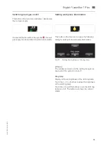
Page 42: ...illumination This button in the main menu opens the following dialog for setting of the workpiece illumination Fig 37 Setting the brightness of the ring lamp Close The window is closed and the setting changes are kept even if the system is shut off Ring lamp Display of the set brightness of the LED ring lamp Touch the buttons to adapt the brightness of the LED ring lamp Touch the On Off buttons to...

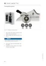
Page 43: ...h as laser parameters pulse shapes that are not yet saved 2 Turn the LASER key switch B to the 0 posi tion C 3 Set the main switch A MAIN POWER to the 0 position 4 If applicable close the valves for the inert gas in the gas cylinder fittings NOTE Remove the key and store it in a location that is only accessible to authorized persons ...

Page 44: ...eck and correct the current parameter settings NOTE To ensure smooth and safe operation it is highly recommended to keep a log book for each device In this log book you should record all malfunc tions and unusual events as well as all servicing and repair tasks It is also recommended to use the electronic log function This requires the following SERVICE MENU ENGINEER Ensure that date and time are ...

Page 45: ...lso be welded through and through i e into the inside which however can only be achieved with careful preparation of the weld right from the wax up stage or by grinding to form a V shaped extended joint or a double V butt joint through the use of wire as filler metal see Fig 41 This applies in particular to smaller cross sections such as clasps bars and sublingual bars In cases where there is no r...

Page 46: ... wire is to be applied through the so called melting bath method Every laser pulse is to be directed such that approx 1 3 is aimed at the wire tip and approx 2 3 at the metal surface so the metal dripping from the wire strikes a molten surface Fig 39 The spot welds should overlap by approx 80 so the centre of the previous spot is always covered Fig 40 An example of welding parameters the exact val...

Page 47: ...0 BegoPal 300 wire 61165 Bio PontoStar PontoStar G wire BegoPal S Bio PontoStar wire or 61157 weld in appropriately ground BegoPal PontoStar G wire 61150 castings with precise fit BegoStar ECO BegoStar ECO wire 61171 High gold content LFC veneerable Bio PlatinLloyd Bio PlatinLloyd wire 61161 PontoRex G PontoRex G wire 61151 PontoRex H PontoRex G wire 61151 PlatinLloyd KF PlatinLloyd KF wire 61158 ...

Page 48: ... 50003 Wirobond C Wiroweld CoCrMo wire 50005 50003 Wirobond SG Wiroweld CoCrMo wire 50005 50003 Wiron 99 Wiroweld NC NiCrMo wire 50006 Wiroweld CoCrMo wire Wirocer Plus Wiroweld NC NiCrMo wire 50006 Wiroweld CoCrMo wire Non precious alloys not veneerable Wirolloy Wiroweld NC NiCrMo wire 50006 Wiroweld CoCrMo wire Titanium Titanium Pure titanium Gr 2 wire 50008 direct butt joint possible Material t...

Page 49: ...he weld In this way vapour deposition on the optical compo nents is avoided and a loss in power is prevented effectively The gas flow continues as long as the foot switch is held down half way or more The inert gas can thus be used economically by means of the foot switch The vapours produced during welding and the inert gas are extracted and filtered continuously Selecting welding parameters corr...

Page 50: ...etal prepared on both sides with a single V or double V butt joint Notes To protect the model place a thin silver foil under the welding point It reflects the radiation and prevents sulphur vapours that form during the decomposition of plaster When the seam is filled the fitting accuracy should be checked from time to time by putting the piece back on the model Avoiding stress When the seam is fil...

Page 51: ... cracks appear next to the wire during welding of the deepest layers grind them and weld them closed at a low energy level layer by layer otherwise the homogeneity of the weld is not guaranteed Note It is advantageous initially to weld on the precious filler metal on the entire surface on the non precious metal side in order to produce a buffer layer In this way the gold wire flows better during f...

Page 52: ...not available for a single V butt joint a gap can be filled by inserting a thin plate which is cast or a wire beaten flat can be used and welded homogeneously all around with spot welds that overlap by approx two thirds in each case Fig 43 This method does not result in full surface welding but circular deep penetration welding Fig 43 Connecting crowns b Precious metal to non precious metal Prepar...

Page 53: ...king plate in position on the crown in the parallelometer and fix with wax Here the attachment parts can first be fixed at the opposite corners with initial spot welds without further parallelization After that complete the joint on the outer circumference with welding wire making sure always to weld only short partial seams on opposite sides see Fig 46 Fig 46 Welding parallel attachment Welding i...

Page 54: ... build it up spot by spot Finally the built up material can be reworked and smoothed at the same time Welding bar sleeve with partial denture The bar sleeves are frequently so thin that they melt thoroughly at an excessively high energy level due to the laser welding pulse and are joined to the bar This welding work is carried out more successfully on the plaster model Fill the silicone mould for ...

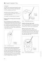
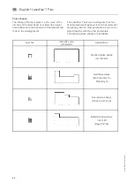
Page 55: ... result The LaserStar T plus plus welding laser has four fixed preset pulse shapes which can be selected for processing like the other parameters and can be stored together with the other parameters The following pulse shapes are available Symbol Intensity curve schematic Applications Standard pulse shape incl titanium Gold base alloys Bio PontoStar XL PlatinLloyd Non precious alloys Wirobond Wiro...

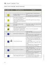
Page 56: ...rable In this cases the symbol is displayed in addition to the specific error symbol Example water flow too low Interlock error messages In the case of malfunctions that cause the device to turn off for security reasons the button is displayed in addition to the specific error symbol Example permissible cooling water temperature exceeded The device will only work after eliminating the fault and su...

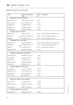
Page 57: ... the tank too low Check water level Fill the tank to the maximum mark with DI water If the symbol keeps on being indicated ple ase contact the service department 6 The water flow is too low Check if there is a kink in the cooling hose Check the circulating pump and permeabi lity of the filter by disconnecting the return line from the filter and feeding it directly into the supply tank Clean the co...

Page 58: ... entered value for the focus setting could not be rea ched Switch the device off and on again several times and note the time it takes for the power supply unit to discharge see error message 2 Check connections If the message keeps on being indicated please contact the service department No Symbol Type Meaning Explanation Measures ...

Page 59: ...and openings cloth to be mounted by the customer 18589 5 Spare parts Flow plate glass between laser lamp and laser rod 16075 6 Lens protective glass Ø 38 mm 15990 7 Lens 120 mm 15988 8 Splash protection window 100x50x2mm3 15686 9 Protective glass for the ring light 18590 10 Pedal switch electric complete 18591 11 Fuse 16 A 18592 NOTE The following wear parts will not be replaced free of charge wit...

Page 60: ...ty equipment see homonymous section NOTE By no means use strong cleaning agents e g cleaning powder or solvents DANGER All maintenance work not explicitly described in this manual may only be carried out by specially trained and authorized service engineers even when the laser is switched off Daily maintenance or after strongly splashing welding Check the protective glass in front of the lens at l...

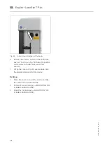
Page 61: ...pped with the ring light option Fig 49 Removing ring light 3 Loosen the three Allen screws see arrows A in Fig 50 the third screw is not visible and pull the ring light downward arrow B 4 Unscrew the knurled ring A at the underside of the lens counterclockwise remove it and holding it as horizontal as possible take it out of the working chamber Fig 50 Removing protective glass 5 Replace the old gl...

Page 62: ... window The observation window consists of two glasses The laser protective window yellowish green window on the outside position A in the figure below prevents the emission of laser radiation and ultra violet light The splash protection window B on the inside of the working chamber protects the laser pro tective window from soiling and damaging If the view of the working chamber is impaired the s...

Page 63: ...in Fig 53 shows the position of the screw on the left side seen from behind 7 Lift up the cover and put it upside down onto the prepared space left of the device Refitting 1 Place the cover on top of the device and tigh ten it with the four Allen screws 2 Remount the microscope MOUNTING THE STEREO MICROSCOPE 3 Adjust the microscope ADJUSTING THE STEREO MICROSCOPE ...

Page 64: ...sition Fig 55 Plug in of funnel tube Refilling deionised water 2 Plug in the quick release coupling of the funnel tube into the corresponding socket see arrow A in Fig 56 3 Fill in deionized water up to the max level see arrow in Fig 55 4 If the device is filled up for the first time switch on the main switch so that the pump starts up and the air is removed from the coolant circuit The water leve...

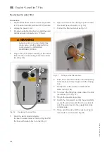
Page 65: ...n and remove the closing cap of the water filter insert see arrow B in Fig 56 7 Pull out the filter cushion see Fig 57 Fig 57 Pulling out the filter cushion 8 Push in the new filter cushion into the opening to the block and close it again with the closing cap 9 Fill the tank to the maximum mark with DI water see Fig 54 10 To remove the filling hose press down the lock see arrow C in Fig 57 11 Plug...

Page 66: ...59 and dispose of it properly Fig 59 Removing the filter fabric A Filter fabric B Spark protection mat C Filter frame WARNING Do not clean the filter Beating or blowing out with compressed air will destroy the filter medium The pollutants attached to the filter will get into the air of the working area 4 Clean the spark protection mat see B in Fig 59 using a damp cloth and a mild soap solu tion wh...

Page 67: ...recious metal 270 3 0 1 0 yes Precious metal 10 Defects in precious metal crowns 280 4 0 1 2 11 Weld precious metal bridge 290 10 0 0 4 12 Align precious metal bridge 290 6 0 1 0 no 13 Build up contact points precious metal 290 4 0 1 2 yes 14 Precision pins for friction to telescopic crowns pre cious metal 280 4 0 1 2 no 15 Increase friction of secondary crowns precious metal 260 2 5 1 0 no 16 Dol...

Page 68: ...Clasp break in partial denture 270 4 0 0 6 2 Retentions to PD Partial denture retentions to partial denture 270 6 0 0 7 3 PA to PD Precious metal secondary crown to partial denture 290 9 0 0 6 4 Weld PA bridge Weld together precious metal bridge 290 10 0 0 4 5 cont Point PA Build up contact points precious metal 290 4 0 1 2 6 Frict sec crown Increase friction of secondary crowns precious metal 260...

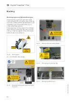
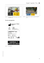
Page 69: ... location of the signs is shown in the following figures These signs may not be removed If one of these signs has been removed for any reason or if it is missing it must be reapplied in the same position before the device is switched on Fig 60 Warning signs A on both sides of the device Fig 61 Warning and information signs at the back of the device Fig 62 Warning sign in the working chamber Fig 63...

Page 70: ...76 DB en 03 355 00032 English LaserStar T Plus en Fig 65 Warning and information signs on top of the excitation unit Fig 66 Warning signs at power supply of lamp and SCU Device designation Fig 67 Type plates ...

Page 71: ...n the ID plate of the BEGO device indicates that the device in accordance with the European directive on waste electrical and electronic equipment may not be disposed of as normal domestic waste As a customer you contribute to the protection of the environment when you dispose of the device correctly Disposal in Germany BEGO offers you a disposal solution for all BEGO devices sold and put into ope...

Page 72: ... operations 41 Filling up and connecting 28 Fire hazard 8 First putting into operation 29 Fix bond on the model 47 Footswitch 14 Function test of the EMERGENCY STOP button 33 Function test of the safety switch of the working chamber door 32 G General Functions 18 General information 53 General instructions 31 General instructions concerning the service menus 18 H Handling deionised water cooling w...

Page 73: ...e shape 37 Saving laser parameters memory manager 34 Select pulse shape 36 Selecting welding parameters correctly 46 Service menu ENGINEER 20 Service menu USER 19 Service menus 18 Serving and maintenance 9 Setting managing laser parameters 33 Setting Combinations 64 Setting workpiece illumination 39 Shutter status display 17 Specific safety information 9 Status error messages causes and remedy 54 ...

Page 74: ......

Page 75: ......

Page 76: ...BEGO Bremer Goldschlägerei Wilh Herbst GmbH Co KG Technologiepark Universität Wilhelm Herbst Straße 1 28359 Bremen Telefon 49 421 2028 0 Telefax 49 421 2028 100 E Mail info bego com www bego com ...

Reviews: