26
A
-en
English
⋅
en
Protective gas option
In addition to the operating controls and installations
listed up to this point, the protection gas option also
has the following component:
A quick coupler connection (nominal width 7.2) for a
nitrogen cylinder located on the back of the device.
Set the pressure regulating valve to 1.0 to 1.2 bar
and connect the device to the nitrogen cylinder
using a quick coupler (not included in the scope of
delivery).
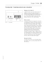
A control panel for protective gas is located between
the power switch and the display on the front of the
device. The protective gas is added with the switch.
The switch has 3 switching states:
•
Position I (switch turned to the top) and green
LED on
•
Position 0 (center position): no LED on
•
Position II (switch turned to the bottom): no LED
on
Switch position I:
The protective gas function, including the pre-flood
function (rinsing the polymerization chamber with
nitrogen for 30 seconds before light exposure) is
activated.
After 30 seconds, the flash-light will start; simultane-
ously, the polymerization chamber will be flooded for
another 60 seconds.
The yellow LED (labelled "ok") will be on during the
inflow of protective gas; if the pressure is insufficient
(< 0.8 bar) or if there is no gas flow, the yellow LED
will go off and the red LED (labelled "def.") will light
up. After a total of 90 sec. (60 sec after the light
exposure has started), the flooding with N2 will be
stopped automatically. The yellow LED will go off.
Once the programmed light exposure time has
elapsed, the flooding with N2 will be stopped as
well, even if the light exposure time was < 60 sec.
Switch position 0:
The protective gas option is turned off,
Switch position II:
The protective gas function is activated, however
without pre-flooding. The protective gas flows into
the chamber with the start of the light exposure. The
polymerization chamber will be flooded with the
protective gas during the entire polymerization time.
The yellow LED (labelled "ok") will be on during the
inflow of protective gas; if the pressure is insufficient
(< 0.8 bar) or if there is no gas flow, the yellow LED
will go off and the red LED (labelled "def.") will light
up (like with switch position i). Once the
programmed light exposure time has elapsed, the
flooding with N2 will be stopped as well.
The gas flow amounts to approx. 10-11 litres per
minute (with 1.0 to 1.2 bar at the reducing valve) and
the atmospheric oxygen in the tray will be displaced.
This will prevent oxygen inhibitation and the surface
of the workpieces will cure without oxygen inhibi-
tation.
Notes:
Complete curing with protective gas only works
when the Plexi trays are used.
Use nitrogen N2, technical standard with purity level
2.6 (purity level 99.6%) or higher.
The switch positions cannot be changed during the
program sequence.
WARNING
Risk of injury
Use a pressure reduction valve,
max. allowed pressure 8 bar.
Summary of Contents for Otoflash
Page 1: ...Gerätedokumentation Miteinander zum Erfolg ...
Page 2: ......
Page 4: ......
Page 5: ...ORIGINAL BETRIEBSANLEITUNG Otoflash de Deutsch Otoflash ...
Page 19: ...TRANSLATION OF THE ORIGINAL OPERATING INSTRUCTIONS Otoflash en English Otoflash ...
Page 33: ...TRADUCTION DE LA NOTICE ORIGINALE Otoflash fr Français Otoflash ...
Page 47: ...TRADUCCIÓN DEL MANUAL ORIGINAL Otoflash es Español Otoflash ...
Page 61: ...TRADUZIONE DELLE ISTRUZIONI ORIGINALI Otoflash it Italiano Otoflash ...
Page 75: ......
Page 76: ......
Page 77: ......

