5
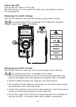
3. Connecting test leads:
• Connect the common (COM) test lead to the circuit before connecting
the live lead
• After measurement, remove live lead before removing the common
(COM) test lead from the circuit
4. Symbol “OL” is displayed on LCD when the measurement is out of range.
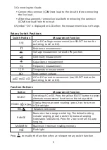
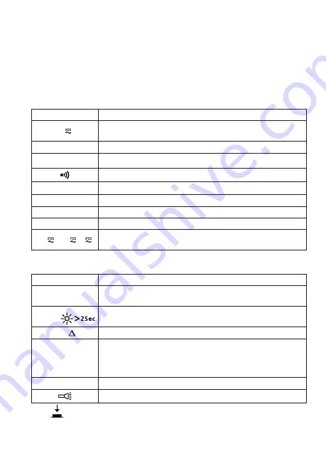
Rotary Switch Positions
Switch Position
Measurement Function
V
AC or DC voltage measurement (use SELECT button for
switching to AC or DC).
e
Resistance measurement
G
Voltage measurement of diode PN junction
Continuity measurement
E
Capacitance measurement
Hz
Frequency measurement
°C °F
Temperature measurement
NCV
Non-contact voltage
μA mA A
AC or DC current measurement (use SELECT button for
switching to AC or DC).
Function Buttons
Button
Measurement Function
SELECT
Switching AC or DC. Press the yellow SELECT button to select
alternate measurement functions on the rotary switch.
HOLD /
Display freezes present reading / press 2 sec to turn on
LCD backlight.
REL
Relative zero mode
RANGE
Manual or Auto range switching. The default setting
is Auto ranging, press to switch to manual ranging
(selectable resolutions). Press for 2 sec to return to auto
ranging.
MAX/MIN
Maximum / minimum reading memory.
Flash light
Press
to enable the function when at relevant rotary switch function.
Summary of Contents for 0095969800341
Page 2: ......
Page 25: ...19 F1 9V ba tte ry F2 ...
Page 26: ......
Page 50: ......
Page 74: ......
Page 98: ......
Page 121: ...19 F1 9V ba tte ry F2 ...
Page 122: ......
Page 146: ......
Page 169: ...19 F1 9V ba tte ry F2 ...
Page 170: ......
Page 193: ...19 F1 9V ba tte ry F2 ...
Page 194: ......
Page 217: ...19 F1 9V ba tte ry F2 ...
Page 218: ......
Page 241: ...19 F1 9V ba tte ry F2 ...
Page 242: ...20 ...
Page 266: ......
Page 289: ...19 10 A indgangsterminal F2 sikring 11 A H 1000 V hurtig sikring 10 38 mm F1 9V ba tte ry F2 ...
Page 290: ......


