6
BL3300 SERIES MANUAL 01/28/2013
SECTION 2
UNPACKING AND INSTALLATION
! WARNING
2.3
PROTECTIVE EARTH CONNECTION
This equipment is provided with a protective earth connection as one level of protection against
electrical shock hazards. The metallic chassis of this equipment
must be connected to the installation
site safety earth. This is typically the green/yellow wire supplied in most line cords. This is in addition
to the input neutral.
Three phase units utilize a four wire input plus the safety earth. Unless stated
otherwise, all 3 phase inputs are of a “WYE” configuration. The Neutral connection is required for
input harmonic reduction and EMI filter return. The unit may be operated without the neutral however
this is not recommended.
IMPORTANT NOTE:
If this unit is to be installed as part of a permanent power source with wiring distributed in a building
the user is responsible for conformance to local electrical codes. The National Electrical Code
(NEC)section 250 requires that all separately derived AC power sources ( generators, invertors, etc.
) must have one conductor tied to earth. This is similar to the concept of the neutral conductor in
domestic power distribution systems. This connection may be provided by connecting the input neutral
to the output neutral ( neutral carried through )or connecting the output neutral to the chassis ground.
The output neutral of this equipment is internally isolated from the input neutral. Consult local codes
and a qualified electrician.
2.4
3 PHASE INPUT POWER REQUIREMENTS
The BL3300 series power supplies within the model number range C2 to C6 require the use of “back-
up” fuses to provide the required protection when operating from line to line voltages above 277 volts.
This is due to the interrupt rating of the circuit breaker used. The fuses are located on the front panel
of the input power chassis. The front panel circuit breaker is employed as a switch only for these
units. Fuses must be replaced with the same type and rating only.
! WARNING
REMOVE INPUT POWER BEFORE REMOVING OR REPLACING FUSES
FUSE REPLACEMENT IS DESCRIBED ON THE FOLLOWING PAGE
Summary of Contents for BL3300 Series
Page 9: ...3 BL3300 SERIES MANUAL 01 28 2013 ALL MANUAL ADDENDUMS WILL FOLLOW THIS PAGE ...
Page 15: ...9 BL3300 SERIES MANUAL 01 28 2013 SECTION 2 UNPACKING AND INSTALLATION ...
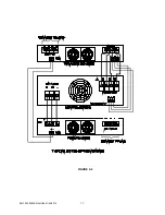
Page 17: ...11 BL3300 SERIES MANUAL 01 28 2013 FIGURE 2 2 ...
Page 20: ...14 BL3300 SERIES MANUAL 01 28 2013 ...
Page 33: ...3 PHASE POWER CHASSIS MECHNICAL OUTLINE ...
Page 34: ...BL3300 CONTROL CHASSIS MECHANICAL OUTLINE ...
Page 35: ...BL33XX SERIES SINGLE PHASE POWER CHASSIS OUTLINE DRAWING 19 0 TYP 17 TYP 7 0 MAX ...
Page 54: ...6 1 SECTION 6 PARTS LIST AND DRAWINGS f ...
Page 56: ......
Page 57: ......
Page 58: ......
Page 60: ......
Page 62: ......


