10
BL3300 SERIES MANUAL 01/28/2013
SECTION 2
UNPACKING AND INSTALLATION
2.5
INPUT POWER CONSIDERATIONS
FOR SINGLE PHASE INPUTS
( C8 and C9 units
)
2.5.1
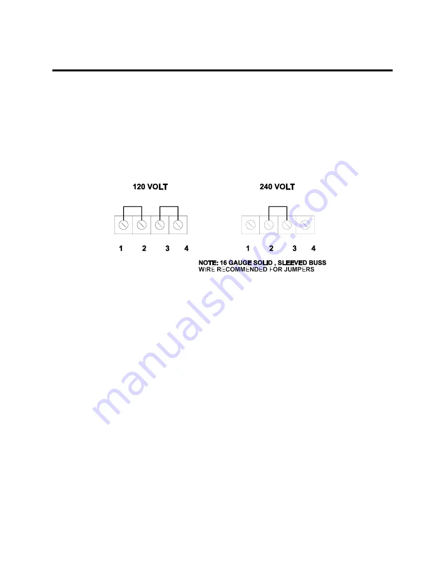
SETTING THE INPUT VOLTAGE RANGE
This device is equipped with a dual primary input transformer. These windings may be series
connected for a 240 nominal input or in parallel for a 120 nominal input. Internal taps allow finer
adjustment and are set at the factory. The diagram below illustrates the voltage selecting terminals
located on the rear of the single phase input power chassis. Replace safety covers after wiring.
2.6
UNITS WITH T3 OR T3D OPTIONS
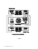
The diagram of figure 2-2 on the following page illustrates chassis inter-connection for units provided
with the T3 or T3D options. The T3D units are dual range versions of the standard T3 type. As shown
in figure 2-2 , this option includes an additional 3.5 inch high chassis to house the external
transformers and range relay for T3D units. This is referred to as the transformer chassis. The output
relay that controls application of power to the load is also moved to the transformer chassis. Additional
inter-wiring is required to bring relay and fan power to the transformer chassis. Units supplied with T3
options will include additional terminal blocks with 6/32 hardware for this purpose. The location may
vary for special units
Units supplied with T3 options may vary slightly depending on actual customers requirements.
Units with a 0 to 270 Vac or 0 to 300 Vac are considered standard. Units supplied with other
voltages will be assigned a 4 digit engineering number. T3 units require some special operating
considerations. Refer to section 3 of this manual for additional operating consideration for T option
units.
Summary of Contents for BL3300 Series
Page 9: ...3 BL3300 SERIES MANUAL 01 28 2013 ALL MANUAL ADDENDUMS WILL FOLLOW THIS PAGE ...
Page 15: ...9 BL3300 SERIES MANUAL 01 28 2013 SECTION 2 UNPACKING AND INSTALLATION ...
Page 17: ...11 BL3300 SERIES MANUAL 01 28 2013 FIGURE 2 2 ...
Page 20: ...14 BL3300 SERIES MANUAL 01 28 2013 ...
Page 33: ...3 PHASE POWER CHASSIS MECHNICAL OUTLINE ...
Page 34: ...BL3300 CONTROL CHASSIS MECHANICAL OUTLINE ...
Page 35: ...BL33XX SERIES SINGLE PHASE POWER CHASSIS OUTLINE DRAWING 19 0 TYP 17 TYP 7 0 MAX ...
Page 54: ...6 1 SECTION 6 PARTS LIST AND DRAWINGS f ...
Page 56: ......
Page 57: ......
Page 58: ......
Page 60: ......
Page 62: ......


