13
BL3300 SERIES MANUAL 01/28/2013
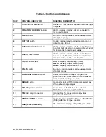
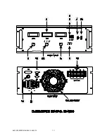
Table 3-1 Controls and Indicators
REF#
CONTROL / INDICATOR
FUNCTION / DESCRIPTION
1
LINE CIRCUIT BREAKER
Located on input chassis, applies or removes input
line power.
2
CONSTANT CURRENT
indicator
L.E.D. indicates protective circuit is activated to
limit output current.
3
FREQ
control
Multi-turn control provides continuous adjustment
of output frequency.
4
OUTPUT
switch
Controls internal relay to connect and dis-connect
output voltage to load.
5
OVERLOAD LATCH
indicator
L.E.D. indicates protective circuit is activated due
to output short circuit. Line power must be cycled of
for 30 seconds to reset power supply
.
6
OVER TEMP
indicator.
L.E.D. indicates protective circuit is activated due
to excessive internal temperature. automatic reset
once temperature return to a safe value.
7
Digital Panel Meters
VOLTS:
displays output voltage (RMS)
AMPS:
displays output current (RMS)
FREQ:
displays output frequency (Hz)
8
VOLTS
control
Multi-turn control provides continuous adjustment
of output voltage.
9
LINE DROP COMP.
trim pots
Allows for correction of output voltage that is
proportionate to current. Used to trim out resistive
drops due to load wiring. See text.
10
RANGE
switch
Optional for units with T3D option only. select one
of two output voltage ranges.
11
TB1
DC power connector
Connects to +/- 250Vdc from input chassis.
DC inter-connect wires supplied with unit.
12
TB2
AC output connector
terminal block for connection to output load.
Requires 1/4" hardware.
13
REMOTE PRGM
connector
Optional computer interface. May be either RS-232
( DB9 ) or IEEE-488 type connector.
14
GND ( Protective Earth )
1/4 “ stud for connecting safety earth. ( a.k.a.P.E.)
Summary of Contents for BL3300 Series
Page 9: ...3 BL3300 SERIES MANUAL 01 28 2013 ALL MANUAL ADDENDUMS WILL FOLLOW THIS PAGE ...
Page 15: ...9 BL3300 SERIES MANUAL 01 28 2013 SECTION 2 UNPACKING AND INSTALLATION ...
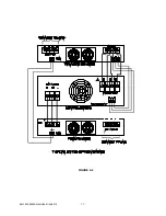
Page 17: ...11 BL3300 SERIES MANUAL 01 28 2013 FIGURE 2 2 ...
Page 20: ...14 BL3300 SERIES MANUAL 01 28 2013 ...
Page 33: ...3 PHASE POWER CHASSIS MECHNICAL OUTLINE ...
Page 34: ...BL3300 CONTROL CHASSIS MECHANICAL OUTLINE ...
Page 35: ...BL33XX SERIES SINGLE PHASE POWER CHASSIS OUTLINE DRAWING 19 0 TYP 17 TYP 7 0 MAX ...
Page 54: ...6 1 SECTION 6 PARTS LIST AND DRAWINGS f ...
Page 56: ......
Page 57: ......
Page 58: ......
Page 60: ......
Page 62: ......


