17
BL3300 SERIES MANUAL 01/28/2013
SECTION 3
OPERATION
DRIVING MOTORS
Driving an AC motor presents a special problem. Most motors require a starting current that is several times
higher than the running current. This current may last for a few cycles to several seconds depending on the
construction and mechanical load on the motor. This current is sometimes referred to as the motor’s “locked
rotor” current. This current is not to be confused with the in rush current that usually occurs over the course
of one or two cycles of the AC waveform.
The BL series fold back current limiting can be an advantage when starting motors. During the starting period,
the motor will attempt to draw excessive power from the power source. The fold back circuit will reduce the
output voltage in order to maintain the maximum output current for the range in use. During this time the
current supplied to the motor will remain sinusoidal, this allows the motor to start rotating. Once the motor
reaches it’s normal operating speed, it generates the required “back EMF” and the supply current drops off
to the nominal “run” current for the motor.
A good way to start an induction motor is to set the ac power supply output to zero volts and set the output
switch on. With the motor connected, quickly use the front panel volts control to “ramp up “ the output voltage.
This will limit the locked rotor current and “soft start” the motor.
DRIVING NON-LINEAR LOADS
Loads utilizing rectifiers and SCRs interact with the AC power source and have a profound effect on the
distortion of the output waveform. Consider the use of a bridge rectifier followed by a capacitive filter, the input
current to this type of circuit is drawn in large “gulps” whenever the voltage across the capacitor falls below
the peak of the input waveform. This current is limited only by the series impedance present in the wiring and
capacitor . The impedance of large electrolytic capacitors is very small. This action causes a current waveform
with a peak value that may be several times the RMS value. This ratio of peak current to RMS current is
known as “ Crest Factor”. High values of crest factor cause distortion of the AC voltage waveform.
The amount of distortion incurred is dependant on many factors and is beyond the scope of this manual. It
should be noted that this type of load may cause the output waveform to exhibit “flat topping” . This should
not be associated with a defect of the power source. Most “real world” electric distribution systems exhibit this
distortion for this reason
.
OUTPUT NOISE
Because the BL series uses a high frequency PWM conversion technique, a certain amount of output noise
or ripple is to be expected. The amount of noise present on the output voltage waveform from this unit varies
somewhat with the load. Maximum noise levels are present when there is no load applied. In any event, the
amount of noise present should not constitute a problem for properly designed equipment. If the devices being
tested are disabled by the noise present on the output waveform, then serious consideration should be given
to the design of the unit being tested as it may not pass the European EMI tests.
In special cases where the output noise is objectionable, an external line filter can be added to the output of
the unit. Please note that most line filters are not intended to be used at 400Hz. If the noise level is interfering
with low level measurements a linear type AC source should be considered. For more information on linear
sources, contact Behlman Sales.
T3 & T3D UNITS
Adding the external transformer chassis will affect the regulation specifications of the power supply when
measured at the transformer secondary. This is due to the winding resistance of the transformer and will vary
depending on which transformer is used. Higher voltage transformers tend to exaggerate this effect. An
internal “boost” circuit as been added to the control chassis to minimize this drop in voltage versus load
current. The boost circuit works very similar to the “Line Drop Compensation” provided on the control chassis
( see operating instructions).
Summary of Contents for BL3300 Series
Page 9: ...3 BL3300 SERIES MANUAL 01 28 2013 ALL MANUAL ADDENDUMS WILL FOLLOW THIS PAGE ...
Page 15: ...9 BL3300 SERIES MANUAL 01 28 2013 SECTION 2 UNPACKING AND INSTALLATION ...
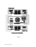
Page 17: ...11 BL3300 SERIES MANUAL 01 28 2013 FIGURE 2 2 ...
Page 20: ...14 BL3300 SERIES MANUAL 01 28 2013 ...
Page 33: ...3 PHASE POWER CHASSIS MECHNICAL OUTLINE ...
Page 34: ...BL3300 CONTROL CHASSIS MECHANICAL OUTLINE ...
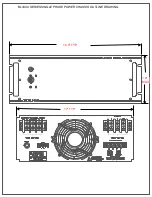
Page 35: ...BL33XX SERIES SINGLE PHASE POWER CHASSIS OUTLINE DRAWING 19 0 TYP 17 TYP 7 0 MAX ...
Page 54: ...6 1 SECTION 6 PARTS LIST AND DRAWINGS f ...
Page 56: ......
Page 57: ......
Page 58: ......
Page 60: ......
Page 62: ......


