20
BL3300 SERIES MANUAL 01/28/2013
SECTION 4
MAINTENANCE AND ADJUSTMENTS
4.2.2
CONTROLLER CARD POTENTIOMETER ADJUSTMENTS
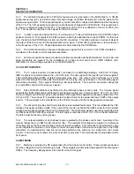
Since certain potentiometer adjustments affect other associated potentiometer settings, a sequence of
adjustments must be followed to ensure the proper setting of each potentiometer within the three groups
comprising the unit. The three groups: frequency, voltage, and current, are listed below in the sequence to
be performed within each group. R15,16,19 & 34 are located on the mother board. R29,61,& 58 are
located on the individual phase control cards ( PWA 106-945-000)
FREQUENCY
VOLTAGE
CURRENT
POT. PARA
POT. PARA
POT. PARA
R15
4.2.3
R29
4.2.6
R34
4.2.9
R16
4.2.4
R61
4.2.7
4.2.10
R19
4.2.5
R58
4.2.8
4.2.3
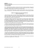
LOW FREQUENCY TRIM (45 Hz R15)
1) Connect frequency counter to rear panel
N
A and NEUT terminal strip.
2) Turn FREQ control fully ccw.
3) Set circuit breaker to ON.
4) Set OUTPUT switch to ON
5) Set selector switch to
N
A.
6) Adjust VOLTS control until volts meter indicates 10 Vrms minimum.
7) Adjust 45 Hz potentiometer R15 until frequency counter indicates 45 Hz.
4.2.4
HIGH END FREQUENCY TRIM (500 Hz R16)
1) Turn FREQ control fully cw.
2) Adjust 500 Hz potentiometer R16 until frequency counter indicates 500 Hz.
4.2.5
FREQUENCY METER ADJUST (Hz-METER R19)
1) Turn FREQ control fully ccw.
2) Adjust Hz-METER potentiometer R19 until front panel meter indicates 500 Hz.
4.2.6
FULL SCALE OUTPUT VOLTAGE ADJUST (R29)
1) Using DVM set to ac volts, connect it accross rear panel
N
A and NEUT on output terminal strip.
2) Turn VOLTS control fully ccw.
3) Set circuit breaker of power chassis to ON.
4) Set OUTPUT switch of power chassis to ON.
5) Adjust R29 until DVM indicates 135 VMS..
Summary of Contents for BL3300 Series
Page 9: ...3 BL3300 SERIES MANUAL 01 28 2013 ALL MANUAL ADDENDUMS WILL FOLLOW THIS PAGE ...
Page 15: ...9 BL3300 SERIES MANUAL 01 28 2013 SECTION 2 UNPACKING AND INSTALLATION ...
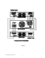
Page 17: ...11 BL3300 SERIES MANUAL 01 28 2013 FIGURE 2 2 ...
Page 20: ...14 BL3300 SERIES MANUAL 01 28 2013 ...
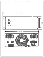
Page 33: ...3 PHASE POWER CHASSIS MECHNICAL OUTLINE ...
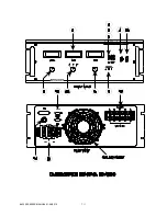
Page 34: ...BL3300 CONTROL CHASSIS MECHANICAL OUTLINE ...
Page 35: ...BL33XX SERIES SINGLE PHASE POWER CHASSIS OUTLINE DRAWING 19 0 TYP 17 TYP 7 0 MAX ...
Page 54: ...6 1 SECTION 6 PARTS LIST AND DRAWINGS f ...
Page 56: ......
Page 57: ......
Page 58: ......
Page 60: ......
Page 62: ......


