25
BL3300 SERIES MANUAL 01/28/2013
SECTION 5
THEORY OF OPERATION
5.7 MISCELLANEOUS
5.7.1
Internal heat-sink temperature is monitored via an sensor mounted to the extrusion. The sensor is
normally open but will close when a safe temperature is exceeded. When this sensor closes the PWM signal
is eliminated by setting the same latch used by the short circuit protection.
5.7.2
The optional GPIB board provides an isolated computer interface for remote control of frequency,
voltage, and the output relay. The GPIB card will also provide read-back of current and voltage to the GPIB.
THEORY OF OPERATION FOR GPIB \ RS232 INTERFACE
( refer to dwg # 106-945-000 )
All BL series power supplies including the “I” option contain an additional circuit card providing a computer
interface. This interface may be one of two standards, IEEE 488 or RS232. This card controls the supply
output voltage, frequency , and range as well as providing data back to the controlling computer. Operation
of the interface card is described in the following section.
The heart of the interface card is the 80C196 micro processor U17. This device used in conjunction with a
programmable memory/logic device U18, provides all the required communication functions. RS232
communications are handled directly by U17 while IEEE 488 protocol is handled by buss controller U19. U19
is an industry standard TMS 9914. Data stored in the U18 EEPROM determines which communication proto
call is selected. EEPROM data also determines scale factor and other set up parameters which are
determined by the actual model and size of the unit being controlled.
Programmed output voltage and frequency data is applied to serial D/A convertors. These convertors provide
a 0 to 10Vdc output that is applied to the analog remote inputs of the host unit. Control of these parameters
is as described in the theory of operation for the power source.
Read back of output current and voltage is obtained by monitoring the internal circuits of the power source.
These dc signals are selected via U1 a two channel “one of four” de-multiplexor. Note that the actual number
of channels and inputs used depends on the model of the power source. Again , this is determined by the
EEPROM data . The outputs of U1 are applied to a set of voltage to frequency convertors. The output of these
converters range from 100 Hertz to 200 Hertz. These frequencies are measured by the microprocessor and
scaled to provide the proper current and voltage data to the controlling computer. The output frequency of the
power supply is measured by monitoring its internal clock signal via U4. This input is labeled “Hz-FDBK”.
Control of the output on/off relay and range relay is provided via the interface board via dry contacts from
K1 and K2. These small PCB mounted relays are controlled by U18. All signals coming to and exiting from
the interface board and the power source are optically isolated. This adds a measure of safety and prevents
ground loops between the controlling computer and power source circuitry.
All firmware for the interface card is written in INTEL’s PL/M format. A list of supported commands and
syntax is provide in appendix B and C of this manual.
Summary of Contents for BL3300 Series
Page 9: ...3 BL3300 SERIES MANUAL 01 28 2013 ALL MANUAL ADDENDUMS WILL FOLLOW THIS PAGE ...
Page 15: ...9 BL3300 SERIES MANUAL 01 28 2013 SECTION 2 UNPACKING AND INSTALLATION ...
Page 17: ...11 BL3300 SERIES MANUAL 01 28 2013 FIGURE 2 2 ...
Page 20: ...14 BL3300 SERIES MANUAL 01 28 2013 ...
Page 33: ...3 PHASE POWER CHASSIS MECHNICAL OUTLINE ...
Page 34: ...BL3300 CONTROL CHASSIS MECHANICAL OUTLINE ...
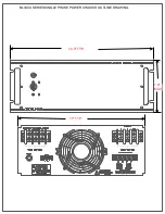
Page 35: ...BL33XX SERIES SINGLE PHASE POWER CHASSIS OUTLINE DRAWING 19 0 TYP 17 TYP 7 0 MAX ...
Page 54: ...6 1 SECTION 6 PARTS LIST AND DRAWINGS f ...
Page 56: ......
Page 57: ......
Page 58: ......
Page 60: ......
Page 62: ......

