5
SECTION 3
P1351 AC POWER SUPPLY OPERATING INSTRUCTIONS
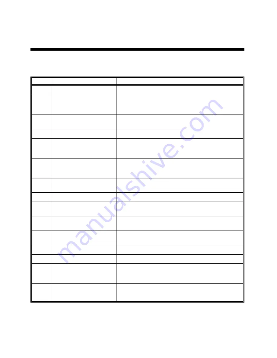
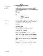
Before operating this equipment the user should become familiar with the controls and indicators provided.
These are summarized in the table 3-1. Refer to figure 3-1 (previous page) for locations.
ITEM#
DESIGNATION
FUNCTION / DESCRIPTION
1
POWER
switch
Controls input line power.
2
RANGE SELECT
switch
Selects output voltage range: HI = 0 -270 Vac
Lo = 0-135 Vac
HIGH
LED illuminates when 270V range is selected.
3
VOLTS
adjust control
Multi-turn control provides continuous adjustment of the unit's
output voltage. See item 4.
4
VOLTS
display
LED readout of the units output voltage .
5
display
SELEC
T switch
Push button toggles the
FREQ/AMPS
display function.
The
FREQ
&
AMPS
LEDs lamps indicate which quantity is
displayed. See item 8.
6
FAULT
LED
CONSTANT CURRENT
LED
Indicates unit disabled due to overload ( short circuit ).
Indicates the unit is in current limit due to overload.
7
FREQ
adjust control
Multi-turn control provides continuous adjustment of the
power supply’s output frequency. See item 8.
8
FREQ / AMPS
display
LED readout of units output current or frequency.
9
output
ON/OFF
switch
Push button switch toggles the power supply output on and
off via an internal relay.
10
front panel
OUTPUT
Recessed "Banana" safety type receptacles provide front
panel load connections.
11
rear panel
AC OUTPUT
Screw type output terminals connected in parallel to the front
panel output.
12
REMOTE
option
Optional remote control board. See manual section 5.
13
AC input connector
IEC-20 type input power receptacle.
14
AC line fuse
Screw type fuse receptacle.
WARNING replace fuse with
same type and rating only!
25A 132V "Slo-Blo". See
manual text for more information.
15
Fan exhaust
Heated air is exhausted at the rear of the unit. A minimum
clearance of 4 inches is required for proper cooling.


