background image

10

SUPER-X PRO CX2310

3. APPLICATIONS

+

BEHRINGER accepts no responsibility for any damage or destruction of loudspeakers arising

from improper or incorrect use of the SUPER-X PRO and in particular from actions which are in

contravention with the clearly stated procedures given in this manual.

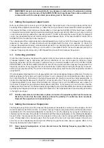
3.2 Setting the input and output levels

Both inputs offer a gain or loss of up to 12 dB. Normally, the output level on the mixing console and the input

sensitivity of the amplifiers are identical, i.e. 0 dB at the mixing console corresponds with 0 dB at the amplifiers.

This means that there is full control over the amplifiers. In this case the SUPER-X PRO should have no effect

on the system level and all input and output level settings should be set at 0 dB. Where e.g. a home recording

or disco console is being used with an operating level of -10 dBV but the amplifiers need +4 dBu for complete

control, then an additional gain of 12 dB must be provided between them. In this case the INPUT control of the

SUPER-X PRO should be set to the maximum.
The output levels of the single bands can be raised/lowered by as much as 6 dB. To achieve a linear frequency

response in the system, all output levels should be adjusted with the help of an analyzer. To check the

crossover frequencies and levels, mute all outputs except for one, and play back pink noise over the system at

an appropriate volume level. When you now switch on the adjacent band, the level measured around the

crossover frequency should go up by 3 dB. Repeat this process for all crossover frequencies.

3.3 Correcting problems

Check the entire frequency response of the system. Rooms have quite an impact on the frequency response

of speaker systems, due to resonance and various reflections, so you cannot expect to achieve a linear

frequency response right from the start. To achieve this, you need an equalizer such as the ULTRA-CURVE

PRO DSP8024 or the ULTRA-GRAPH GEQ3102. Look for drop-outs around the crossover frequencies! If the

frequency response is very irregular, then it can make sense to grade adjust it using the frequency crossover,

before using an equalizer (EQ). The errors in the crossover frequency must then be as far as possible corrected

using the EQ.
If the loudspeaker diaphragms in a multi-way system are not exactly aligned along a vertical axis, the varying

distances between the sound source and the listener result in phase errors and cancellations (also known as

the “comb filter effect”). Particularly in the higher frequencies it is important, due to the shorter wavelengths, to

position the diaphragms above each other and not next to each other. The various types of construction used

in individual systems (horns, bass reflex cabinets etc.) still give rise to run time differences, even where the

front sides of all systems are aligned vertically above each other. In this case a run time correction must be

made by electronic means. This can be done by using a delay function. Run time differences can be compensated

by delaying the frequency bands over a range of milliseconds. This helps avoid loss of sound quality, particularly

in the high tone ranges.

+

Runtime correction is not the same as phase correction. If a speaker system has the same run

times then it also has the same phases (unless the polarity of a cable has been reversed).

However the opposite is not necessarily true.

3.4 Setting the crossover frequencies

The frequency range from which the crossover frequencies can be selected, can be one of two ranges—from 44

to 930 Hz and from 440 Hz to 9.3 kHz. To set the crossover frequencies, please first read the manufacturers’

specifications for the individual loudspeaker components. To use the capacity of your system at its best you

should set up the crossover frequencies in accordance with the frequency diagrams on the individual loudspeaker

boxes. Further, the crossovers should not lie on peaks or drop-outs. Look for a range with the flattest possible

curve. If folded bass horns are being used, then the length of the horn path must also be taken into account,

since the run time displacements arising from differing long paths can also have a negative effect on the

frequency development (see chapter 3.3).

+

Never operate loudspeakers or horn drivers below the limiting frequency specified by the

manufacturer!

Summary of Contents for SUPER-X PRO CX2310

Page 1: ...SUPER X PRO CX2310 www behringer com Version 1 0 March 2001 User s Manual ENGLISH ...

Page 2: ...appliances including amplifiers that produce heat Power Source The appliance should be connected to a power supply only of the type described in the operating instructions or as marked on the appliance Grounding or Polarization Precautions should be taken so that the grounding or polarization means of an appliance is not defeated Power Cord Protection Power supply cords should be routed so that th...

Page 3: ...ost important member of our team With your highly competent encouragement and suggestions for new products you have greatly contributed to shaping our company and to making it successful In return we guarantee you an uncompromising level of quality manufactured under ISO9000 certified management system excellent technical and audio characteristics and an extremely favorable price All this makes it...

Page 4: ... adjustment s Individual phase reverse switches for instant phase correction s Switchable 25 Hz subsonic filter on each input for low frequency driver protection s Servo balanced gold plated XLR connectors for all inputs and outputs s Ultra high precision ALPS potentiometers for ultimate accuracy and repeatability s Ultra low noise audio operational 4580 amplifiers for outstanding sound performanc...

Page 5: ...nly in stereo systems but in cinemas discotheques and concert halls As customers have become more demanding they can even be found now in such simple products as TV sets Why With the same sound pressure low frequency sound waves have a much greater amplitude oscillation range than high frequency waves When a single loudspeaker tries to produce bass and treble frequencies at the same time a so call...

Page 6: ...f features we have provided the active controls with suitable light emitting diodes These displays help you to keep track of what is happening even in dark stage environments Additionally all the switches on the front panel are illuminated and can thus show which functions are presently active There are two labels in the form of strips located above the controls The text of the upper label indicat...

Page 7: ...lanced XLR connectors for the low band output signal 3 XOVER FREQ switch These switches are used to switch between the control ranges on the front panel LOW HIGH XOVER FREQ control The range is either 44 to 930 Hz or 440 Hz to 9 3 kHz 4 INPUT connectors These are the balanced XLR connectors for the input signal 5 MODE switch In stereo 2 way operation the switch must be depressed Please refer to th...

Page 8: ... range 6 to 6 dB 5 LOW PHASE INVERT switch This switch is used to reverse the polarity of the low output 6 LOW MUTE switch This is used to mute the low band 7 MID HIGH XOVER FREQ control This control governs the crossover frequency between the mid and high bands 8 MID OUTPUT control This is used to control the output level of the mid band over the range 6 to 6 dB 9 MID PHASE INVERT switch This rev...

Page 9: ...in the frequency response occur In addition every room has different size and quality characteristics These strongly influence the sound response since resonances and reflections in the different frequency ranges can also lead to reductions or increases in the sound picture You will need suitable equipment in order to be able to recognize and compensate for these features 3 1 Tools You will need a...

Page 10: ...e to grade adjust it using the frequency crossover before using an equalizer EQ The errors in the crossover frequency must then be as far as possible corrected using the EQ If the loudspeaker diaphragms in a multi way system are not exactly aligned along a vertical axis the varying distances between the sound source and the listener result in phase errors and cancellations also known as the comb f...

Page 11: ...s boxes which are separate from each other can mutually disrupt each other where their sound waves meet what happens here can be easily imagined if you throw two stones into water first separately and then stuck together 4 AUDIO CONNECTIONS As a standard the BEHRINGER SUPER X PRO CX2310 is equipped with electronically servo balanced inputs and outputs The circuit design features automatic hum supp...

Page 12: ...lter Type Linkwitz Riley 24 dB octave state variable Mono Mode Frequencies x1 x10 Low High 44 to 930 Hz 440 Hz to 9 3 kHz Low Mid 44 to 930 Hz 440 Hz to 9 3 kHz Mid High 440 Hz to 9 3 kHz Stereo Mode Frequencies x1 x10 Low High 44 to 930 Hz 440 Hz to 9 3 kHz POWER SUPPLY Mains voltage USA Canada 120 V 60 Hz U K Australia 240 V 50 Hz Europe 230 V 50 Hz General Export Model 100 120 V 200 240 V 50 60...

Page 13: ...30 days of receipt of the product at BEHRINGER 2 If the product needs to be modified or adapted in order to comply with applicable technical or safety standards on a national or local level in any country which is not the country for which the product was originally developed and manufactured this modification adaptation shall not be considered a defect in materials or workmanship The warranty doe...

Reviews: