


7
SUPER-X PRO CX2310
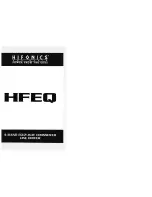
2. CONTROL ELEMENTS
1
INPUT control.
This control adjusts the input gain over the range from -12 to +12 dB.
2
LOW CUT switch.
This switch activates the 25 Hz high-pass filter. It has a side gradient of 12 dB/octave
and is used to protect your bass loudspeaker.
3
LOW/HIGH XOVER FREQ. control.
This control governs the crossover frequency between the low and
high bands.
4
LOW OUTPUT control.
Controls the output level of the low band over the range from -6 to +6 dB.
5
LOW PHASE INVERT switch.
This switch reverses the polarity of the low output.
6
LOW MUTE switch.
This is used to mute the low band.
7
HIGH OUTPUT control.
This controls the output level of the high band over the range from -6 to +6 dB.
8
HIGH PHASE INVERT switch.
This switch reverses the polarity of the high output.
9
HIGH MUTE switch.
This is used to mute the high band.
10
XOVER FREQ. control.
This control governs the crossover frequency between the low signal and the
subwoofer signal (10 to 235 Hz).
11
GAIN control.
This is used to set the subwoofer output volume at the SUBW. OUT output.
12
PHASE INVERT switch.
This switch reverses the polarity of the subwoofer output signal.
13
MUTE switch.
This mutes the subwoofer output signal.
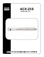
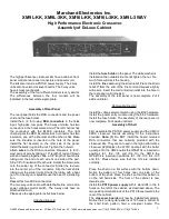
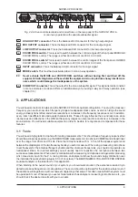
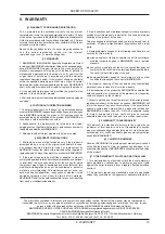
Fig. 2.2: Active control elements and connections on the rear panel of the SUPER-X PRO in
stereo 2-way operation with separate subwoofer signal
1
HIGH OUTPUT connectors.
These are the balanced XLR connectors for the high band output signal.
2
LOW OUTPUT connectors.
These are the balanced XLR connectors for the low band output signal.
3
XOVER FREQ. switch.
These switches are used to switch between the control ranges on the front
panel LOW/HIGH XOVER FREQ. control. The range is either 44 to 930 Hz or 440 Hz to 9.3 kHz.
4
INPUT connectors.
These are the balanced XLR connectors for the input signal.
5
MODE switch.
In stereo 2-way operation the switch must be depressed. Please refer to the text on the
rear panel of the equipment.
+
Never activate the MODE and XOVER FREQ. switches without having first switched off the
equipment. Switching between these while the equipment is in use produces heavy interference
noise which could damage the loudspeakers or the system.
6
SUBW. OUT connector.
This is the balanced XLR output for the mono subwoofer signal. This signal is
constant in mono and stereo mode and provides an additional means of providing 2- and 3-way operation
(see chapter 3.5).
7
IEC-RECEPTACLE.
This is the mains connection of the SUPER-X PRO. A suitable mains cable is
included with the equipment.
8
FUSE HOLDER /VOLTAGE SELECTOR.
Before connecting the equipment to the mains supply, please
check that the voltage display conforms with your mains voltage supply. When replacing the fuse, make
sure you use another one of the same type. With many units the fuse holder can be set in one of two
positions, in order to switch between 230 V and 115 V. Please note: if you wish to operate a unit outside
Europe, then a stronger fuse must be used.
9
SERIAL NUMBER.
Please take the time to complete and return the warranty card within 14 days of the
date of purchase, otherwise you will lose the right to the extended warranty. Or just use our online-
registration (www.behringer.com).