background image

12

SYSTEM 55

Quick Start Guide

13

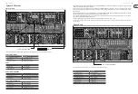
Modules

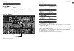
Your System 55 has three rows of modules

Top Row

(1) 

914 Fixed Filter Bank (FFB). 

(2) 

923 Filters and Noise Sources. 

(3) 

904B High Pass Filter (HPF). 

(4) 

 904A Low Pass Filter (LPF).

(5) 

992 Control Voltages.

(6) 

&

 (7) 

(10)


(12)


     902 Voltage Controlled Amplifiers (VCA).

(8) 

 &

 (9) 

(14)


&


(15)


     911 Envelope Generators (EG).

(13)


     911A Dual Trigger Delay (DTD).

Middle Row

(1) 

(5) 

     921A Oscillator Driver. 

(2) 

(4) 

(6) 

(8) 

     921B Voltage Controlled Oscillators (VCO).

(9) 

921 VCO/LFO.

(10)


960 Sequential Controller.

(11)


CM1A – MIDI interface.

(1)

(2) (3) (4) (5) (6) (7) (8) (9)

(10) (11) (12) (13) (14) (15)

(1) (2) (3) (4) (5) (6) (7) (8)

(9)

(10)

(11)

Bottom Row

(1) 

(4) 

(7)

      CP3A – O.

(2) 

(5) 

(8)

      CP3A – M.

(3) 

(6)  

995 Attenuators.

(9) 

903A Random Signal Generator.

(10)


CP35 Attenuator / Voltage Source / Multiple.

(11)


961 Interface.

(12)


962 Sequential Switch.

Further information on all modules can be found on their individual Quick Start Guides at www.behringer.com/downloads.html

System 55 -  Getting Started

HARDWARE SETUP


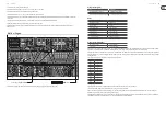
Make all the connections in your system as described in the individual patches. Keep the System 55 power turned off when making any connections. 
Ensure your sound system is turned down. 
Turn on the System 55 before turning on any power amplifiers and turn it off last. This will help prevent any turn on or turn off “pops or thumps” in your speakers. 

WARM UP TIME


We recommend leaving 30 minutes or more time for the System 55 to warm up before recording or live performance. (Longer if it has been brought in from the cold.) 

This will allow the precision circuits time to reach their normal operating temperature and tuned performance.  


(1)

(2)

(3) (4)

(5)

(6) (7)

(8)

(9)

(10)

(11)

(12)

Summary of Contents for SYSTEM 55

Page 1: ...Quick Start Guide SYSTEM 55 Complete System 55 Modular Synthesizer with 38 Modules MIDI to CV Converter and 2 EURORACK GO cases V 1 0...

Page 2: ...Gruppen Lake Tannoy Turbosound TC Electronic TC Helicon Behringer Bugera Oberheim Auratone Aston Microphones y Coolaudio son marcas comerciales o marcas registradas de MusicTribe Global Brands Ltd Mu...

Page 3: ...lectrocution Utilisezuniquementdesc blesd enceintesprofessionnels dehautequalit avecfichesJackmono6 35mmoufiches verrouillagesd j install es Touteautreinstallationou modificationdoit treeffectu euniq...

Page 4: ...relative alla garanzia limitata di MusicTribe consultare online i dettagli completi su musictribe com warranty Informazioni importanti DISCLAIMER LEGALE GARANZIA LIMITATA Aviso Terminaismarcadoscomos...

Page 5: ...gd Alle handelsmerken zijn eigendom van hun respectievelijke eigenaren Midas KlarkTeknik Lab Gruppen Lake Tannoy Turbosound TC Electronic TC Helicon Behringer Bugera Oberheim Auratone Aston Microphone...

Page 6: ...eniamiproducenta 14 U ywa jedyniezalecanych przezproducenta lubznajduj cych si wzestawie w zk w stojak w statyw w uchwyt w isto w Wprzypadku pos ugiwaniasi w zkiemnale yzachowa szczeg ln ostro no wtra...

Page 7: ...ource Multiple 11 961 Interface 12 962 Sequential Switch Further information on all modules can be found on their individual Quick Start Guides at www behringer com downloads html System 55 Getting St...

Page 8: ...is also daisy chained The selected waveform from each oscillator is fed to one of the CP3A M mixers which then feeds the 904A LPF S triggers are fed to a multiple and then to two of the 911 EGs s trig...

Page 9: ...ignal Output 2nd 902 Signal Input 904B Signal Output 3rd 902 Signal Input 3 x 902 Signal Output CP3A M Mixer Inputs 1 3 CPO3A M Mixer Output Your Mixer Amplifier DAW Voltage Control Amplitude CM1A s t...

Page 10: ...changes constantly at the speed of the 921sine wave the 921 should be in Sub mode speed can be adjusted to suit The main part of the sound comes from the 904A LPF whose Fixed Control Voltage and Rege...

Page 11: ...l Output 1st 902 Signal Input 904B Signal Output 2nd 902 Signal Input Signal Outputs of both 902s Right hand CP3A M Inputs Right hand CP3A M Output Your mixer amplifier DAW Voltage Control amplitude 9...

Page 12: ...cionamento Defeituoso CasoseufornecedorMusicTriben oestejalocalizado nasproximidades voc podecontatarumdistribuidor MusicTribeparaoseupa slistadoabaixode Suporte emmusictribe com Seseupa sn oestiverna...

Page 13: ...e interference by one or more of the following measures Reorient or relocate the receiving antenna Increase the separation between the equipment and receiver Connect the equipment into an outlet on a...

Page 14: ...We Hear You...

Reviews: