background image

19

ULTRALINK UL2000B

5. INSTALLATION

5.1 Operating information

The quality of the wireless transmission depends on various local factors as well as the degree of
radiation and reception at transmitter and receiver, unlike the signal transmission over cable. To
minimize the risk of interference, take the following suggestions into account for a smooth operation
of the wireless system.

5.1.1 Attach the transmitter

For optimal operation of the transmitter, please observe the following when attaching the transmitter:

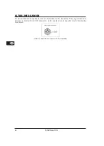
Use only the provided headset and ensure that the mini XLR-connector is fastened correctly.

Attach the transmitter to a belt by using the provided clip instead of simply placing it into a
pocket, for instance. The optimal freedom of movement is guaranteed by fastening the transmitter
to one's back or side.

Make sure the headset's cable is not wrapped around or comes into contact with the antenna; this
would result in an impairment of the transmission.

Avoid direct body contact with the antenna to attain a maximum range.

The headset's microphone capsule should be aligned towards the speaker at approximately 2-
5 cm from the mouth. Ideally, the capsule should be kept off-centered to mouth and nose to
avoid the conveyance of breathing sounds.

5.1.2 General information

Always make sure that the devices are not operated in direct proximity of large metallic
surfaces (radiators, metal racks, reinforced concrete walls and similar).

The devices should always be at a height of at least 1 m (3 ft.) off the ground.

To assure good reception in many different positions, we advise against having the antennae
point at a 90-degree angle. Instead, antennae should be arranged at an angle of no more
than 40° in respect to one another.

To assure interference-free reception, ideally there should be no large objects placed between
the transmitter and the receiver. Not only the size but also the type of material play a role in
determining how strong signal interference will be!

Keep a minimum distance of 5 meters between transmitter and sender to avoid signal
overmodulation.

When using multiple transmitters, the distance between the transmitting units should be at least
20 cm to avoid crosstalk (i.e. intermodulation).

Replace used batteries ahead of time. A dropout would be unacceptable at a production,
hence, do not wait until the battery indicator warns you that the battery needs to be replaced.

Use the presets to guarantee an interference-free transmission of multiple transmitters and
receivers on up to 8 channels.

If you want to install your ULR2000 in a rack, please read the following chapter; there you can
find all the necessary information.

5.2 Installation in a rack

The ULR2000’s antennae are located in the front of the unit. This allows unproblematic installation
in a rack.

Each unit is delivered with a rack bracket and a connecting joint. This way, you can choose:

1.

If you wish to install only one unit in a rack, mount a rack bracket to one of the sides. In this
case, you will not need the included connecting joint. Now, install one side of the receiver into
the rack.

2.

To install 2 receivers in a rack, first connect the two receivers to one another at the bottom
using the connecting joint. Mount one rack bracket on the left side of one unit and one rack
bracket on the right side of the other unit. Now, both ULR2000s can be installed in a rack.

5. INSTALLATION

Summary of Contents for ULTRALINK UL2000B

Page 1: ...User s manual Version 1 0 August 2006 ULTRALINK UL2000B ...

Page 2: ...ere they exit from the apparatus 10 Only use attachments accessories specified by the manufacturer 11 Use only with the cart stand tripod bracket or table specified by the manufacturer or sold with the apparatus When a cart is used use caution when moving the cart apparatus combination to avoid injury from tipping over 12 Unplug this apparatus during lightning storms or when unused for long period...

Page 3: ...ating the Transmitter 12 3 2 1 Turning the transmitter on 12 3 2 2 Channel setting 13 3 2 3 Setting your own frequency 13 3 2 4 Preset 14 3 2 5 Mic Gain 15 3 2 6 Auto Mute 16 3 2 7 Turning the transmitter off 17 3 3 Status query 17 3 3 1 Battery condition and transmission channel 17 3 3 2 Transmission frequency 17 3 3 3 Preset 17 3 3 4 Mic Gain 17 3 3 5 Auto Mute 18 3 5 ULB2000 level setting 18 4 ...

Page 4: ...cing one another Additionally you have the option of storing 8 of your own frequencies in a user preset thus individually addressing your own needs Determining which microphone is assigned to which receiver is done either by observing the transmission channel in the display or by comparing the transmission frequency In addition the ULTRALINK equipment from BEHRINGER leaves you the option to color ...

Page 5: ...ector Ensure that the antenna has been screwed tightly onto the transmitter The ULB2000 requires a 9 V battery to operate The constant glowing of the LED indicates the operational readiness When the battery is nearly depleted the STATUS LED on the transmitter begins to flash quickly At the same time an inaudible signal is sent to the ULR2000 receiver which then shows LowBat on its display To ensur...

Page 6: ...ained in detail and you will get useful information on how to use them 2 1 1 The front Fig 2 1 ULR2000 s front side POWER To power the ULR2000 on or off keep the POWER button pressed for at least 2 seconds To disconnect the unit from the mains please unplug the power supply Make sure the wall power supply is easily accessible whenever you use the ULR2000 If you mount it in a rack make sure that yo...

Page 7: ... connected to the ANTENNA 1 and ANTENNA 2 connectors 2 1 2 Display Fig 2 2 Closeup of the ULR2000 display antenna symbol These two antenna symbols indicate which antenna signal is currently being processed The left symbol lights up when the signal from the left hand antenna ANTENNA 1 is stronger and the right symbol shows that the signal from the right hand antenna ANTENNA 2 is being processed RF ...

Page 8: ...ts getting weaker the noise increases the signal to noise ratio gets smaller The SQUELCH menu item lets you enter a threshold value in dB for the signal to noise ratio If this ratio gets smaller than the threshold value the receiver automatically mutes the signal ch 2 2 3 2 1 3 The back Fig 2 3 ULR2000 s back The power is supplied via a 12 V connector A matching cable is included in the delivery I...

Page 9: ...ically searches for a transmitter when in SCAN mode For it to work the transmitter e g the ULB2000 must be turned on 1 Press the SET button to get to the menu 2 Press the UP button once to get to SCAN 3 Press the SET button again to get to the SCAN submenu The display shows the current frequency 4 Either press UP or DOWN This way you determine if the scan is going to be performed in the ascending ...

Page 10: ...e ULR2000 recognizes this signal and automatically mutes the output before the transmitter is actually turned off switched to another channel or before it powers down on its own due to battery charge being too low For the Auto Mute function to work it has to be activated on both the transmitter and the receiver Activating deactivating the Auto Mute function 1 Press the SET button to get to the men...

Page 11: ...ay again 2 2 7 PRESET The ULR2000 lets you work with 4 presets each with 8 channels Factory presets Presets 2 3 and 4 In the ULR2000 there are 3 factory presets each with 8 interference free channels That means that all 8 channels of one preset can run simultaneously with 8 different transmitters and receivers without causing mutual interference The channels in the 3 factory presets are all assign...

Page 12: ...programming mode by selecting the digits 9 or 0 or you can get a readout of a specific unit setting SELECTION SWITCH Using a screwdriver you can select different values on the SELECTION SWITCH For example you can select a channel number and the frequency STATUS LED Through repeated blinking the status LED gives the account of the current settings for all parameters We differentiate between 3 diffe...

Page 13: ...lected 0 or 9 the channel selected last remains selected 3 2 3 Setting your own frequency A carrier frequency in the range between 798 1 and 805 9 MHz can be freely selected This frequency is stored in a self assignable user preset Preset 1 The carrier frequency can only be set in 25 kHz steps The frequency you select has to be a multiple of 25 kHz If you select a frequency that is not a multiple ...

Page 14: ...f the LED blinks quickly 5 times the frequency was not stored In this case start anew with step 2 If no entry is made for more than 5 seconds either on the selection switch or by pressing the POWER button the LED blinks quickly 5 times and the programming mode is aborted 8 Disengage the MUTE switch A user assigned frequency is automatically stored in the user preset Preset 1 3 2 4 Preset The ULB20...

Page 15: ...onal blink code is given as a confirmation Successful loading of a preset is signaled with two slow blinks The unit leaves the programming mode If the preset could not be loaded the LED blinks quickly 5 times In this case start anew with step 2 7 After setting the desired preset disengage the MUTE switch 3 2 5 Mic Gain You have the option to adjust the ULB2000 to the level of the signal being tran...

Page 16: ...y charge being too low For the Auto Mute function to work it has to be activated on both the transmitter and the receiver Activating deactivating the Auto Mute function 1 Engage MUTE The transmitter can now be switched into the programming mode 2 Turn the selection switch to 0 and confirm your selection by keeping the POWER switch pressed for 2 seconds As a confirmation the LED blinks slowly once ...

Page 17: ...condition 1 battery is nearly empty 5 battery is fully loaded selcted channel 1 channel 1 is selected 8 channel 8 is selected If the receiver is not powered on no status is indicated Briefly pressing the POWER button will neither turn the transmitter on nor off 3 3 2 Transmission frequency 1 Turn the selection switch to 9 The position of the MUTE switch is irrelevant 2 Briefly press the POWER butt...

Page 18: ...ur mixing console so that the peak LED lights up only occasionally or never at all The EQ controls in the microphone channel should be set to mid travel position to start with To get the sound you want try changing the mic position relative to the sound source or even move the microphone around in the recording room of your studio Adjusting the angle at which walls face the sound source can also b...

Page 19: ...against having the antennae point at a 90 degree angle Instead antennae should be arranged at an angle of no more than 40 in respect to one another To assure interference free reception ideally there should be no large objects placed between the transmitter and the receiver Not only the size but also the type of material play a role in determining how strong signal interference will be Keep a mini...

Page 20: ... M6 machine screws and nuts Be sure that there is plenty of space around the unit for cooling and to avoid overheating please do not place the ULR2000 on top of power amplifiers or other heat emitting equipment If you wish to install more than 2 units in a rack please make sure that there is enough space between them fig 5 1 The lower unit s antennae may not perturb against the upper unit s antenn...

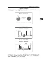
Page 21: ...ent to the balanced connectors Fig 5 2 XLR connections Fig 5 3 1 4 TS connector Fig 5 4 1 4 TRS connector The transmitter cannot be connected with a cable directly to a mixer as is the case with wired microphones The connection between transmitter and the ULR2000 receiver is wireless Then the receiver passes on the signal over a cable connection 5 INSTALLATION ...

Page 22: ...n is required to connect the headset to the transmitter The plug connection is provided by means of mini XLR connectors which ensure a secure operation due to their locking mechanism Abb 5 5 Mini XLR connector of the ULB2000 5 INSTALLATION ...

Page 23: ...LB2000 transmitter under optimal environmental conditions AF characteristics coupled to ULB2000 Noise reduction high performance IRC compander system Pre Deemphase AF frequency response 30 19000 Hz 3dB THD at nom deviation and 1kHzNF 0 4 SNR at peak deviation 105 dB A Noise limiter switching threshold 0 125 µV adjustable Output voltage at nom peak deviation 1kHzNF 9 5 dBu 12 5 dBu balanced XLR and...

Page 24: ...BEHRINGER makes every effort to ensure the highest standards of quality Necessary modifications are carried out without notice Thus the specifications and design of the device may differ from the information given in this manual Technicalspecificationsandappearancesubjecttochangewithoutnotice Theinformationcontainedhereiniscorrectatthetimeofprinting The names of companies institutions or publicati...

Page 25: ... and on the user is encouraged to try to correct the interference by one or more of the following measures Reorient or relocate the receiving antenna Increase the separation between the equipment and receiver Connect the equipment into an outlet on a circuit different from that to which the receiver is connected Consult the dealer or an experienced radio TV technician for help Operation is subject...

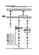
Page 26: ...26 ULTRALINK UL2000B MICROPHONE QUICK START GUIDE MICROPHONEQUICKSTARTGUIDE ...

Reviews: