background image

Installation

2.2.1

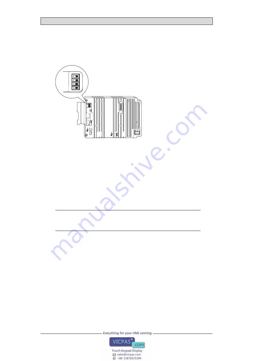
Mode Switches

All mode switches must be in OFF position during operator panel use.
The mode switches should not be touched unless by qualified personnel.

1

24V DC

CF CARD

COM 1

RS422

RS485

COM 2

RS232

10/100

EXP

ANSION

BUSY

MODE

 1   2   3   4

ON  DIP

MODE

 1   2   3   4

ON  DIP

2.2.2

Connections to the Controller

For information about the cables to be used when connecting the operator panel to
the controller, please refer to the help file for the driver in question.

2.2.3

Other Connections and Peripherals

Cables, peripheral equipment and accessories must be suitable for the application
and its environment. For further details or recommendations, please refer to the
supplier.

Caution:

When using a compact

fl

ash card, do not remove the card when the busy indicator is

illuminated.

Beijer Electronics, MAEN773F

10

Summary of Contents for EXTER K100

Page 1: ...EXTER K100 Installation Manual English MAEN773F 2014 11...

Page 2: ...updating this publication Beijer Electronics AB assumes no responsibility for any errors that may appear in this document Read theentireinstallation manual prior to installing and using this equipment...

Page 3: ...calData 11 4 ChemicalResistance 13 4 1 MetalCasing 13 4 2 Screen and Overlay Material 13 4 2 1 Autotex F157 207 13 4 2 2 Screen Surface 14 4 2 3 Screen and Keyboard Protector 15 5 Operator Panel Drawi...

Page 4: ...sa powerful irritant Incase of skincontact wash immediately with plenty ofwater In case of eye contact holdthe eye open ush with plenty of water and get medical attention The gures in this manualserve...

Page 5: ...This product contains a battery this must onlybe changedin an areaknown tobe non hazardous Replace the battery with aCR2450 battery Use of anothertype ofbattery maypresent a risk of re orexplosion Wa...

Page 6: ...roduct to the poweroutlet Peripheral equipment must be appropriate forthe application and location 1 4 During Use Keep the operatorpanel clean Emergency stopand othersafety functions may notbe control...

Page 7: ...h 9 92 inch 382 mm 100 mm 4 0 inch 15 04 inch 2 28 inch Caution The openings on the enclosure are for airconvection Do not cover these openings 2 2 Installation Process 1 Unpackand check the delivery...

Page 8: ...e outer sides ofthe holesandcutaccording to the markings 6 5 mm 35 0 mm For text strip 3 5 mm 35 0 mm 1 38 inch 1 38 inch 0 14 inch 0 26 inch 3 Secure the operator panel in position usingallthe fasten...

Page 9: ...rrors in communication may occur Ensure that the voltage and polarity of the powersource is correct Separate high voltage cables from signal and supply cables Shielded communication cables are recomme...

Page 10: ...the Controller For information aboutthe cables to be used when connecting the operator panelto the controller please refer to the help le for thedriverin question 2 2 3 Other Connections and Periphera...

Page 11: ...lot Compact flash type I and II Real time clock 20 PPM error because of ambient temperature Total maximum error 1 minute month at 25 C Temperature coefficient 0 034 0 006 ppm C2 Real time clock batter...

Page 12: ...XTER K100 Relative humidity 5 85 non condensed Approvals and certifications Information is available on the web site www beijerelectronics com See section ChemicalResistance for more information Beije...

Page 13: ...3 Hydrochloric acid 5 Nitric acid 10 Isopropyl alcohol Phosphoric acid 43 Na hypochlorite 10 Turpentine Note If exposure to any of the above chemicals is demanded itis recommended to first test the c...

Page 14: ...ffin oil Windex1 Cyclohexanol Persil powderin solution1 Wisk Diacetone alcohol Petroleum spirit1 1 Extremely faintglossingof the texture was noted Autotex withstands DIN 42 115 Part2 exposure of up to...

Page 15: ...d Protector For harsh environments and exposure tooutdoorconditions it isrecommended to use a protective lm toguardthe screen and the keyboard from damage These optional parts canbe ordered from Beije...

Page 16: ...Operator PanelDrawings 5 Operator Panel Drawings 5 1 Communication Ports RS 232 RS 422 RS 422 485 RS 485 Ethernet USB Beijer Electronics MAEN773F 16...

Page 17: ...Operator PanelDrawings 5 2 EXTER K100Outline Beijer Electronics MAEN773F 17...

Page 18: ...Operator PanelDrawings 5 3 EXTER K100Text Strip Beijer Electronics MAEN773F 18...

Page 19: ...aid between the panel s chassis and the closest groundingpoint on the door see 3 in drawingabove 3 Connect astrongbut shortgroundingbraid betweenthe doorand the device cabinet see 4 indrawingabove 4 T...

Page 20: ...nithas its shield directly grounded or groundedviaa capacitor Note In many cases connecting the shielded Ethernet cabling to the chassis at both ends is inappropriate Hum or grounding loops canoccur U...

Page 21: ...e shield to the ground via a 0 1 F 250 Vplastic capacitor Both ends are then connected tothe ground in terms ofHF but only connected to the ground at one end in terms ofLF thus avoidingthe 50 Hz groun...

Page 22: ...a large program for controllingthe temperature in the device cabinet An enamel coated steel cabinethasaradiant heatvalue of 5 5 W m2 and degrees C Installinga fan inside the cabinetwill even out the...

Page 23: ...LVaccording to EN 60950 protection against electric shock andUL 950 Note Here is an example that explains why a secure 24 V DC feed can be ruined by mixing 24 V relay contacts with 230 V AC relay cont...

Page 24: ...SB memory stick keyboard or similardevice is plugged in If anumberofunitsare connectedthat have a0 Vand a groundconnection and these are connected to various groundingpoints there is a substantial ris...

Page 25: ...ires may be onthe same levelor require pull up orpull downtoensure that no faultysignals are detected when the busisin restingmode all transmittersare disconnected 1 2 3 4 5 V 0 V 1 K 1 K 120 ohm 120...

Page 26: ...Head office Beijer Electronics AB Box 426 201 24 Malm Sweden www beijerelectronics com 46 40 358600...

Reviews: