GN-9371_2_3 User Manual
Page 102 of (110)
G-series GN-9371_2_3 PIO Rev. 1.02.docx
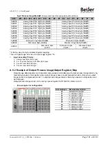
•
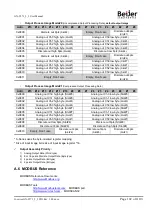
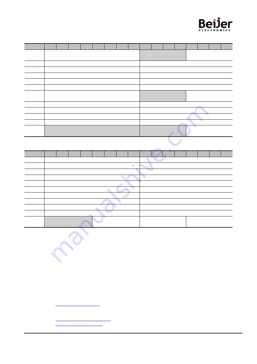
Output Process Image Mode#0
(Uncompressed Output Processing Data),
default output image
Addr.
#15 #14 #13 #12 #11 #10
#9
#8
#7
#6
#5
#4
#3
#2
#1
#0
0x0800
Discrete out 8pts
(Slot#2)
Empty, Don’t care
Discrete out 4pts
(Slot#1)
0x0801
Analog out Ch0 high byte
(Slot#3)
Analog out Ch0 low byte
(Slot#3)
0x0802
Analog out Ch1 high byte
(Slot#3)
Analog out Ch1 low byte
(Slot#3)
0x0803
Analog out Ch2 high byte
(Slot#3)
Analog out Ch2 low byte
(Slot#3)
0x0804
Analog out Ch3 high byte
(Slot#3)
Analog out Ch3 low byte
(Slot#3)
0x0805
Discrete out high 8pts
(Slot#4)
Discrete out low 8pts
(Slot#4)
0x0806
Discrete out 8pts
(Slot#6)
Empty, Don’t care
Discrete out 4pts
(Slot#5)
0x0807
Analog out Ch0 high byte
(Slot#7)
Analog out Ch0 low byte
(Slot#7)
0x0808
Analog out Ch1 high byte
(Slot#7)
Analog out Ch1 low byte
(Slot#7)
0x0809
Analog out Ch2 high byte
(Slot#7)
Analog out Ch2 low byte
(Slot#7)
0x0810
Analog out Ch3 high byte
(Slot#7)
Analog out Ch3 low byte
(Slot#7)
0x0811
Empty, Don’t care
Empty, Don’t care
Discrete out 4pts
(Slot#8)
•
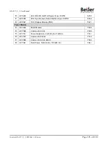
Output Process Image Mode#1
(Compressed Output Processing Data)
Addr.
#15 #14 #13 #12 #11 #10
#9
#8
#7
#6
#5
#4
#3
#2
#1
#0
0x0800
Analog out Ch0 high byte (Slot#3)
Analog out Ch0 low byte (Slot#3)
0x0801
Analog out Ch1 high byte (Slot#3)
Analog out Ch1 low byte (Slot#3)
0x0802
Analog out Ch2 high byte
(Slot#3)
Analog out Ch2 low byte
(Slot#3)
0x0803
Analog out Ch3 high byte
(Slot#3)
Analog out Ch3 low byte
(Slot#3)
0x0804
Analog out Ch0 high byte (Slot#7)
Analog out Ch0 low byte (Slot#7)
0x0805
Analog out Ch1 high byte (Slot#7)
Analog out Ch1 low byte (Slot#7)
0x0806
Analog out Ch2 high byte
(Slot#7)
Analog out Ch2 low byte
(Slot#7)
0x0807
Analog out Ch3 high byte
(Slot#7)
Analog out Ch3 low byte
(Slot#7)
0x0808
Discrete out low 8pts (Slot#4)
Discrete out 8pts (Slot#2)
0x0809
Discrete out 8pts (Slot#6)
Discrete out high 8pts (Slot#4)
0x0810
Empty, Don’t care
Discrete out 4pts
(Slot#8)
Discrete out 4pts
(Slot#5)
Discrete out 4pts
(Slot#1)
* S-Series uses the byte-oriented register mapping.
* Size of input image bit is size of input image register *16.
Output Assembly Priority :
1) Analog Output Data (Word type)
2) 8 or 16 points Discrete Output Data (Byte type)
3) 4 points Output Data (Bit type)
4) 2 points Output Data (Bit type)
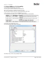
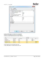
A.6 MODBUS Reference
MODBUS Reference Documents
MODBUS Tools
, MODBUS poll
, MODSCAN32


