GN-9371_2_3 User Manual
Page 81 of (110)
G-series GN-9371_2_3 PIO Rev. 1.02.docx
APPENDIX A - MODBUS INTERFACE
A.1 MODBUS Interface Register / Bit Map
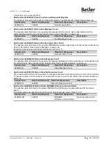
•
Register Map
Start Address
Read/Write
Description
Func.
Code
0x0000 ~
Read
Process input image registers (Real Input Register)
4, 23
0x0800 ~
Read/Write
Process output image registers (Real Output Register)
3, 16, 23
0x1000 ~
Read
Adapter Identification special registers.
3, 4, 23
0x1020 ~
Read/Write
Adapter Watchdog, other time special register.
3, 4, 6, 16,
23
0x1100 ~
Read/Write
Adapter Information special registers.
3, 4, 6, 16,
23
0x2000 ~
Read/Write
Expansion Slot Information special registers.
3, 4, 6, 16,
23
* The special register map must be accessed by read/write of every each address (one address).
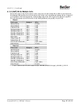
•
Bit Map
Start Address
Read/Write
Description
Func.
Code
0x0000 ~
Read
Process input image bits
All input registers area is addressable by bit address.
Size of input image bit is size of input image register *
16.
2
0x0800 ~
Read/Write
Process output image bits
All output registers area is addressable by bit address.
Size of output image bit is size of output image register *
16.
1, 5, 15
A.2 MODBUS Transmission Mode
Two different serial transmission modes are defined: The RTU mode and the ASCII mode. It defines the bit
contents of message fields transmitted serially on the line. It determines how information is packed into the
message fields and decoded.
A.2.1 RTU Transmission Mode
When devices communicate on a MODBUS serial line using the RTU (Remote Terminal Unit) mode, each 8–
bit byte in a message contains two 4–bit hexadecimal characters. The main advantage of this mode is that its
greater character density allows better data throughput than ASCII mode for the same baudrate. Each
message must be transmitted in a continuous stream of characters.
Start
Address
Function
Data
CRC Check
End
≥ 3.5 chars
1 char
1 char
Up to 252 chars
2 chars
≥ 3.5 chars

