GN-9371_2_3 User Manual
Page 82 of (110)
G-series GN-9371_2_3 PIO Rev. 1.02.docx
A.2.2 ASCII Transmission Mode
When devices are setup to communicate on a MODBUS serial line using ASCII (American Standard Code for
Information Interchange) mode, each 8–bit byte in a message is sent as two ASCII characters. This mode is
used when the physical communication link or the capabilities of the device does not allow the conformance
with RTU mode requirement regarding timers management.
Start
Address
Function
Data
CRC Check
End
1 char
2 chars
2 chars
Up to 252 chars
2 chars
2 chars
CR,LF
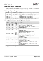
A.3 Supported MODBUS Function Codes
Function
Code
Function
Description
Unicast / Broadcast
1 (0x01)
Read Coils
Read output bit
Unicast
2 (0x02)
Read Discrete Inputs
Read input bit
Unicast
3 (0x03)
Read Holding Registers
Read output word
Unicast
4 (0x04)
Read Input Registers
Read input word
Unicast
5 (0x05)
Write Single Coil
Write one bit output
Unicast / Broadcast
6 (0x06)
Write Single Register
Write one word output
Unicast / Broadcast
8 (0x08)
Diagnostics (Serial Line
only)
Read diagnostic register
Unicast
15 (0x0F)
Write Multiple Coils
Write a number of output bits
Unicast / Broadcast
16 (0x10)
Write Multiple registers
Write a number of output words
Unicast / Broadcast
23 (0x17)
Read / Write Multiple
register
Read a number of input words /
Write a number of output words
Unicast
-
Refer to MODBUS APPLICATION PROTOCOL SPECIFICATION V1.1a
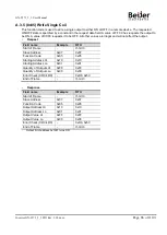
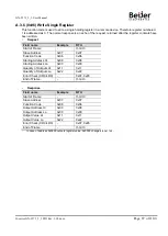
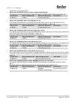
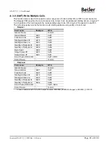
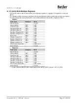
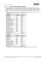
A.3.1 (0x01) Read Coils
This function code is used to read from 1 to 2000 contiguous status of coils in a remote device. The Request
PDU specifies the starting address, i.e. the address of the first coil specified, and the number of coils. In the
PDU Coils are addressed starting at zero. Therefore coils numbered 1-16 are addressed as 0-15. The coils in
the response message are packed as one coil per bit of the data field. Status is indicated as 1= ON and 0=
OFF.
•
Request
Field name
Example
RTU
Start of Frame
-
t1-t2-t3
Slave Address
0x07
0x07
Function Code
0x01
0x01
Starting Address Hi
0x10
0x10
Starting Address Lo
0x00
0x00
Quantity of Outputs Hi
0x00
0x00
Quantity of Outputs Lo
0x0A
0x0A
Error Check (CRC/LRC)
-
0xB8, 0xAB
End of Frame
-
t1-t2-t3

