User Guide Revision 1.12
30
7.
HVAC Specific Feature Setup (Menu 8)
The drive has several features inbuilt into the drive standard operating software that are specific to HVAC applications. The majority of
parameters used in enabling and configuring these functions are contained within menu 8 (See section 11.7). This section is an explanation of
the purpose and operation of each of these functions and guidelines on how each one can be configured.
7.1.
Pump Staging – DOL Cascade
Summary:
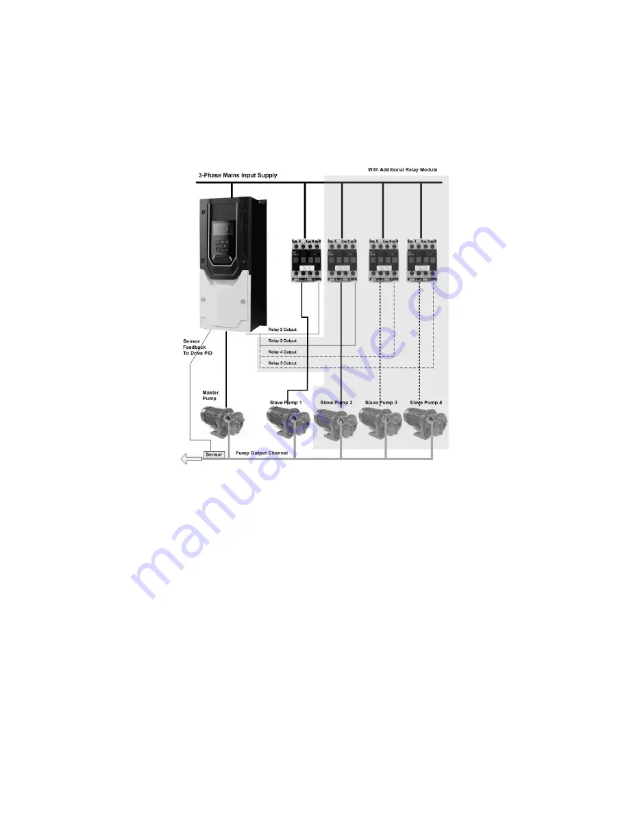
The below illustration shows the use of a drive unit as the controller in a DOL pump staging system. The Master pump in this configuration is
controlled from the output of the drive in variable speed mode with direct relay control of up to four DOL slave pumps as shown below.
Relay 1 on the standard I/O terminals of the Drive (T14 & T15) cannot be used as part of the DOL control but is freely programmable to other
functions through parameter P2-15. Relay 2 on the standard I/O terminals of the Drive (T17 & T18) can be used as the DOL control for the first
slave pump. Relay 2 is set to DOL control by setting parameter P2-18 = 8, or can be used for an alternative function by setting a value other
than 8.
For staging configurations with more than one slave pump an optional extended I/O option module will be required. Options modules are
available allowing up to 3 further slave DOL pumps (giving a maximum of 4 DOL slave pumps) to be connected. Intermittent switching relays
may be required if the contactor voltage or current requirement is outside of the specification of the drive relays (see section 4.7, Control
Terminal Connections).
The system output sensor is connected to the drive analog input 1 or 2 (T6 or T10) and is selected as the feedback to the drive PID controller.
See parameter menu 3 for PID configuration parameters and feedback selection.
Operational Overview:
The pump staging with DOL cascade function is enabled by setting parameter P8-14=1 (Pump staging function select). In addition, the value of
P8-15, ‘Pump staging DOL pump availability’ must be set with the number of Slave DOL pumps available (to a value other than 0).
The drive runs the master pump in variable speed control. The number of Slave DOL pumps available in the system is configured by parameter
P8-15. At a predefined level the slave DOL pumps are brought on-line in sequence to assist the Master variable speed pump. Switch on
sequence is defined by the pump run time clocks (monitored and maintained by the drive) with the least run time pump switched in first. A
pre-defined settle time (Set in P8-19) is observed before any further pumps are switched in or out of the system. This allows the system to
reach a steady operating state before additional pump requirements are assessed. Pump switch off is done at a predefined level in the
sequence of least run time.
The maximum difference in run time between DOL slave pumps can be limited by setting the ‘Pump Staging Duty Switch Over Time’ parameter
(P8-16). When a value is entered into P8-16 the drive will automatically switch off the DOL slave pump with the longest run time and switch in
the pump with the shortest run time once the difference in run times set in P8-16 is exceeded. When P8-16 is set to 0 pump switch-over based
on run time is disabled and switch over is determined only by the threshold limits (demand based).
Duty run time clocks are available to view in P0-19. Clocks are reset by setting parameter P8-20 ‘Pump Staging Master Clock Reset’ to 1 (reset).
Quick Setup Overview:
Summary of Contents for HVAC H2
Page 1: ......
Page 72: ...User Guide Revision 1 12 72 82 H2MAN BE_V1 11...


