background image

|


Technical


Reference


55


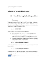
6

­

1

­

4


DISK


BOOT


FAILURE


When


you


can‘t


find


the


boot


device,


insert


a


system


disk


into


Drive


A


and


press


<


Enter


>.


Make


sure


both


the


controller


and


cables


are


all


in


proper


positions,


and


also


make


sure


the


disk


is


formatted.


Then


reboot


the


system.


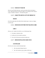
6

­

1

­

5


DISKETTE


DRIVES


OR


TYPES


MISMATCH


ERROR


When


the


diskette


drive


type


is


different


from


CMOS,


please


run


setup


or


configure


the


drive


again.


6

­

1

­

6


ERROR


ENCOUNTERED


INITIALIZING


HARD


DRIVE


When


you


can‘t


initializes


the


hard


drive,


ensure


the


following


things:


1.


The


adapter


is


installed


correctly


2.


All


cables


are


correctly


and


firmly


attached


3.


The


correct


hard


drive


type


is


selected


in


BIOS


Setup


6

­

1

­

7


ERROR


INITIALIZING


HARD


DISK


CONTROLLER


When


this


error


occurs,


ensure


the


following


things:


1.


The


cord


is


exactly


installed


in


the


bus.


2.


The


correct


hard


drive


type


is


selected


in


BIOS


Setup


Summary of Contents for JetBox 8180

Page 1: ...JetBox 8180 User Manual Hardware 0 0 1...

Page 2: ...terial in this document is for product information only and is subject to change without notice While reasonable efforts have been made in the preparation of this document to assure its accuracy we as...

Page 3: ...ts 12 3 2 6 Audio Mic in Line in Earphone out 12 3 2 7 PS 2 12 3 2 8 DC Power Power Switch 12 3 2 9 Reset Button 13 3 3 HW Installation 14 Chapter 4 BIOS 17 4 1 Main Setup 20 4 1 1 System memory 21 4...

Page 4: ...37 4 5 Security setup 38 4 5 1 Clear User Password 40 4 5 2 Password Check 40 4 5 3 Boot Sector Virus Protection 40 4 6 Chipset Setup 41 4 6 1 Northbridge Configuration 41 4 6 2 DRAM Frequency 42 4 6...

Page 5: ...VE 55 6 1 7 ERROR INITIALIZING HARD DISK CONTROLLER 55 6 1 8 FLOPPY DISK CONTROLLER ERROR OR NO CONTROLLER PRESENT 56 6 1 9 KEYBOARD ERROR OR NO KEYBOARD PRESENT 56 6 1 10 MEMORY ADDRESS ERROR 56 6 1...

Page 6: ...port one DVI dual display option and high definition audio into its compact design with DIN rail type mounting the JetBox 8180 communication computer provides flexible connectivities as a result becom...

Page 7: ...Switch x1 Power input DC 12 24V 2 pin terminal block or power jack Power consumption 1 65A maximum 0 86A typical with DC 19V input OS verified Windows 2000 XP WinCE NET XPe Linux OS supported by Beij...

Page 8: ...8 Hardware Feature Chapter 3 Hardware Feature 3 1 Dimensions Following is the mechanical outline for JetBox 8180 145 50 4 102 Picture 1 JetBox 8180 mechanical outline...

Page 9: ...Hardware Feature 9 Picture 2 DIN rail Dimension...

Page 10: ...itch to ON 3 2 2 DVI connector A female DVI I socket is provided DVI Single TMDS Data Link 0 Link 1 CRT signals 3 2 3 Serial Ports The DB9 is standard serials port connector The following tables show...

Page 11: ...e RS 232 RS 422 or RS 485 The default setting is RS 232 JP1 3 2 4 LAN Ports Gigabit Ethernet The RJ45 connector with 2 LED s for LAN The right side LED orange indicates data is being accessed and the...

Page 12: ...3 USBD Pin 4 USBG 3 2 6 Audio Mic in Line in Earphone out Connect the Audio Microphone In Line in Earphone out 3 2 7 PS 2 PS 2 compatible keyboard and mouse interfaces 3 2 8 DC Power Power Switch Powe...

Page 13: ...itch does include a power switch plugging its power adapter into a power outlet then switch power to on when you final installed system hardware device 3 2 9 Reset Button The JetBox has a push button...

Page 14: ...hat the power is disconnected or power switch to off from the system If not this may damage the system 3 The ESD Electricity Static Discharge may be created from human body that touches the board It m...

Page 15: ...Hardware Feature 15 Note 1 The Compact Flash socket supports Compact Flash Modules and Micro Drives b Unscrew back cover and Installing Hard Disk...

Page 16: ...cket for DDR2 RAM Modules You may extend additional memory to the JetBox See as following figure and rear pictures The So DIMM socket supports 512MB to 2GB of DDR2 RAM modules d Installing miniPCIe mo...

Page 17: ...n off the system The BIOS provides a menu driven interface to the console subsystem The console subsystem contains special software called firmware that interacts directly with the hardware components...

Page 18: ...stem Press the Del key to enter the BIOS Setup program and then the main menu will show on the screen Note 3 Change the parameters when you fully understand their functions and subsequence BIOS Functi...

Page 19: ...xit system setup without saving any changes ESC key can be used for this operation Discard Changes Discard changes down so far any of the set questions F7 key can be used this operation Load Optimized...

Page 20: ...ult F9 Optimized Default F10 Save and exit UP Down Arrow Keys To go upward or downward to the desired item 4 1 Main Setup This section describes basic system hardware configuration system clock setup...

Page 21: ...bypass the date and time prompts by creating an AUTOEXEC BAT file For information on how to create this file please refer to the MS DOS manual 4 2 Advanced Setup Select the Advanced tab from the setu...

Page 22: ...he CPU Configuration setup screen varies depending on the installed processor 4 2 2 IDE configuration You can use this screen to select options for the IDE Configuration Settings Use the up and down A...

Page 23: ...And set to Enhanced mode if you are using native OS like Windows XP 2k Available Options Disabled Compatible and Enhanced Default setting Compatible Legacy IDE Channels This field is when set to Compa...

Page 24: ...ower off and then power on without having to reconfigure your hard drive type If you use older hard disk drives which do not support this feature then you must configure the hard disk drive in the sta...

Page 25: ...ine tune the settings to allow for faster boot times Adjust this setting until a suitable timing that can detect all IDE disk drives attached is found Available Options 0 5 10 15 20 25 30 and 35 Defau...

Page 26: ...RQ4 and 2E8H IRQ3 Default setting 3F8H IRQ4 4 2 5 COMB Port Mode Selection These fields item can select RS 232 RS 422 and RS 485 of select port 1 Available Options RS 232 RS 422 and RS485 Default sett...

Page 27: ...BIOS 27 4 2 7 APM Configuration You can use this screen to select options for the USB Configuration...

Page 28: ...efault setting Enabled 4 2 7 2 Video Power Down Mode This field specifies the power conserving state that video subsystem enters after the specified period of display inactivity has expired Available...

Page 29: ...Disabled 4 2 7 4 Suspend Time Out This field specifies the length of time the system waits before it enters suspend mode Available Options Disabled 1 Minute 2 Minute 4 Minute and 8 Minute up to 60 Mi...

Page 30: ...bled Default setting Enabled 4 2 8 2 USB 2 0 Controller Mode This field is configures the USB 2 0 controllers in High speed 480Mbps or Full speed 12Mbps Available Options HiSpeed and FullSpeed Default...

Page 31: ...NVRAM during system boot Available Options Yes No Default setting No 4 3 2 Plug and Plug Aware O S Set to Yes to inform BIOS that the operating system can handle Plug and Play PnP devices Available O...

Page 32: ...device using the interrupt Available Specified IRQ is available to the used by PCI PnP devices Reserved Specified IRQ is reserved for used by Legacy ISA devices Available Options Available and Reserve...

Page 33: ...BIOS 33...

Page 34: ...ot wait for up to 40 seconds if a Ready signal is not received from the IDE drive and will not configure its drive 2 BIOS will not wait for 0 5 seconds after sending a RESET signal to the IDE drive 3...

Page 35: ...12 will be reserved for expansion cards if a PS 2 mouse is not detected Disabled will reserve IRQ12 for expansion cards and therefore the PS 2 mouse will not function Available options Disabled Enable...

Page 36: ...system checks for the device to boot from To access this screen select Boot Device Priority on the Boot Setup screen and press Enter 4 4 8 First Second Third Hard Disk Boot Device Set the boot device...

Page 37: ...e list will show all three hard disk drives attached 4 4 9 Hard Disk Drives Use this screen to view the hard disk drives in the system To access this screen select Hard disk drives on the Boot Setup s...

Page 38: ...a privileged person that can change the User password from the BIOS According to the default setting both access passwords are not set up and are only valid after you set the password from the BIOS Ch...

Page 39: ...he User password until the Supervisor password is set up 4 Enter Advanced BIOS Features screen and point to the Security Option field 5 Select System or Setup i Always a visitor who attempts to enter...

Page 40: ...S Setup Program executes and the computer is turned on If Setup is chosen the password prompt appears if the BIOS executed Available options Setup Always Default setting Setup 4 5 3 Boot Sector Virus...

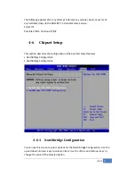
Page 41: ...inue Y N 4 6 Chipset Setup This section describes the configuration of the board s chipset features NorthBridge Configuration SouthBridge Configuration 4 6 1 Northbridge Configuration You can use this...

Page 42: ...Auto 4 6 3 Configure DRAM Timing by SPD SPD represents Serial Presence Detect It is an 8 bit 2048 bits EEPROM built on the SDRAM for 100 MHz frequencies If the installed SDRAM supports SPD function se...

Page 43: ...to the system once the requesting application has been terminated Fixed mode is non contiguous page locked memory allocated during driver initialization to provide a static amount of memory Available...

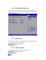
Page 44: ...ns LAN port and audio function 4 6 7 USB Function Select Enabled if a USB device is installed to the system If Disabled are selected the system will not be able to use a USB device Available Options D...

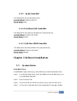
Page 45: ...ld specifies the PXE boot ROM of the onboard LAN chip Available Options Disabled and Enabled Default setting Disabled Chapter 5 Software Installation 5 1 System Driver WIN 2000 XP Driver Installs 945G...

Page 46: ...restart my computer now Installation is done No I will restart my computer later System must be restart then complete the installation Step 5 In the WINDOWS2000 XP you can find the DISPLAYL icon loca...

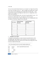
Page 47: ...ox is equipped with a programmable time out period watchdog timer You can use your own program to Enabled the watchdog timer Once you have enabled the watchdog timer the program should trigger the I O...

Page 48: ...t is between 1 to FF timer factors If you want to reset your system when watchdog times out the following table listed the relation of timer factors between time out periods Watchdog Timer Enabled To...

Page 49: ...Out dx al Mov dx 2fh Mov al 28h Set timeout interval as 28seconds and start counting Out dx al Exit extended function mode Mov dx 2eh Mov al 0aah Out dx al Watchdog Timer Trigger After you enabled the...

Page 50: ...tion register CRF5 Bit 3 Sec Min CRF6 Bit 0 7 Count Mov al 07h Out dx al Mov dx 2fh Mov al 08h Select Logical Device 8 of watchdog timer Out dx al Mov dX 2eh Mov al 0f5h Set second as counting unit Ou...

Page 51: ...Note 8 Please refer to the section of the Serial Ports in the Chapter 6 Technical Reference for the detail description of the COM ports register 5 6 1 Initialize COM port Step 1 Initialize COM port in...

Page 52: ...e 0 Step 4 Disabled TXC signal and the bit 0 of the address of offset 4 sets 0 5 6 2 Send out one block data Transmit the data more than two characters Step 1 Enabled TXC signal and the bit 0 of the a...

Page 53: ...t one character 40 PRINT 1 OUTCHR 50 REM Check transmitter holding register and shift register 60 IF INP H3FD AND H60 0 THEN 60 70 REM Disabled transmitter by resetting DTR 80 OUT H3FC INP H3FC AND HE...

Page 54: ...kinds of beep codes in BIOS setup z One indicates that a video error has occurred and the BIOS cannot initialize the video screen to display any additional information This beep code consists of a sin...

Page 55: ...rive type is different from CMOS please run setup or configure the drive again 6 1 6 ERROR ENCOUNTERED INITIALIZING HARD DRIVE When you can t initializes the hard drive ensure the following things 1 T...

Page 56: ...a keyboard set the error halt condition in BIOS Setup to HALT ON ALL BUT KEYBOARD This will cause the BIOS to ignore the missing keyboard and continue the boot procedure 6 1 10 MEMORY ADDRESS ERROR Wh...

Page 57: ...o convert parallel data to a serial format on the transmit side and convert serial data to parallel on the receiver side The serial format in order of transmission and reception is a start bit followe...

Page 58: ...Divisor latch least significant byte 1 Base 1 Divisor latch most significant byte 6 2 1 Receiver Buffer Register RBR Bit 0 7 Received data byte Read Only 6 2 2 Transmitter Holding Register THR Bit 0...

Page 59: ...be 0 Bit 6 Must be 0 Bit 7 Must be 0 6 2 5 Line Control Register LCR Bit 0 Word Length Select Bit 0 WLS0 Bit 1 Word Length Select Bit 1 WLS1 WLS1 WLS0 Word Length 0 0 5 Bits 0 1 6 Bits 1 0 7 Bits 1 1...

Page 60: ...terrupt BI Bit 5 Transmitter Holding Register Empty THRE Bit 6 Transmitter Shift Register Empty TSRE Bit 7 Must be 0 6 2 8 MODEM Status Register MSR Bit 0 Delta Clear to Send DCTS Bit 1 Delta Data Set...

Page 61: ...3 Bit 11 Bit 4 Bit 4 Bit 12 Bit 5 Bit 5 Bit 13 Bit 6 Bit 6 Bit 14 Bit 7 Bit 7 Bit 15 Desired Baud Rate Divisor Used to Generate 16x Clock 300 384 600 192 1200 96 1800 64 2400 48 3600 32 4800 24 9600...

Page 62: ...ears For example if the system has three hard disk drives connected then the list will show all three hard disk drives attached 37 Note 6 that you cannot configure the User password until the Supervis...

Page 63: ...ww beijerelectronics tw Taipei CHINA www beijerelectronics cn Shanghai UK www beijerelectronics com Southampton FRANCE www beijerelectronics com Champlan SWEDEN www westermo com Stora Sundby www weste...

Reviews: