Zigbee1080A user’s manual V6.030
Chapter 2 Components Layout Diagram and a Brief Description
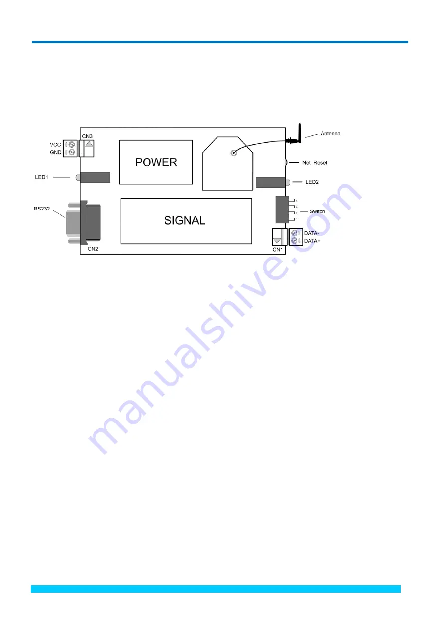
2.1 The Main Component Layout Diagram
2.2 Description the Main Component
2.2.1 Wiring Terminal
GND: power negative
VCC: power positive (unreg10V ~ +30V
DC
)
DATA+: RS485 serial port positive (A)
DATA-: RS485 serial port negative (B)
2.2.2Status Indicator
LED indicator 1: Green light: serial port to receive data.
Red
light:
serial
port
to
send
data.
LED indicator 2: Green light: power indicator, on for normal.
Red light: network connection indicator, the light is flashing when composed network.
2.2.3 Network Reset Button
The network failed to start after re-configure the module, we can press this button to reset the network.
2.2.4 RS232 Interface
RS232 interface: connect this port with PC to configure the XBEE module K1=OFF, K2=ON).
BUY ONLINE at art-control.com/englishs or CALL 86-10-51289836(CN)
4


