background image


Prism Medical Ltd. V1-2014 

19

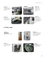
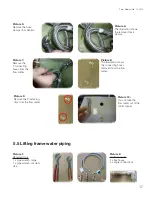
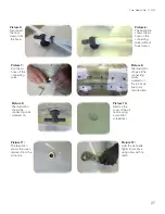
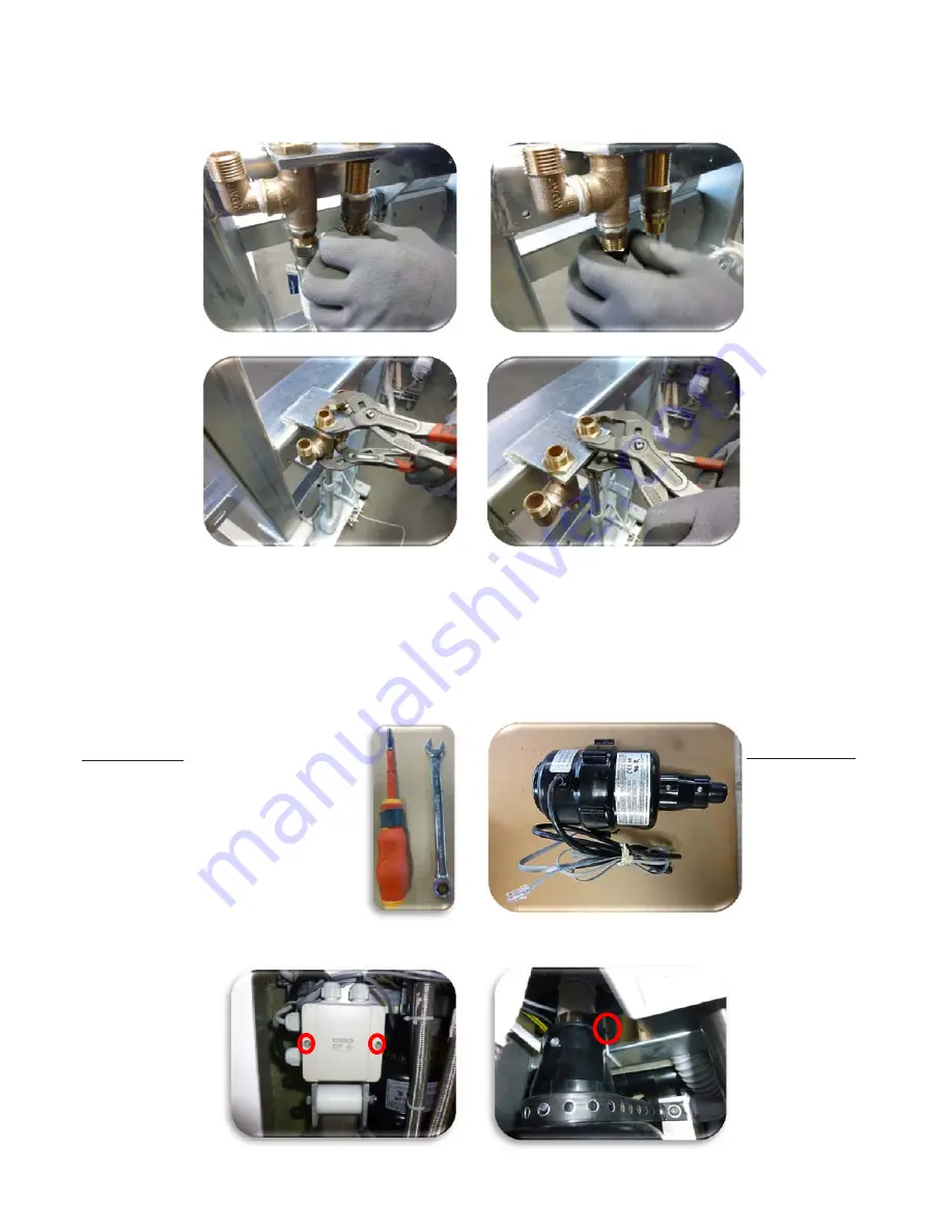
Picture 16: 

Loosen the nuts 

for the hot water 

connection using 

the two pipe 

wrenches.  

Picture 15: 

Loosen the nuts 

for the cold water 

connection using 

the two pipe 

wrenches. 

Picture 14: 

Remove the 

union nut from 

the thread of the 

connection for 

cold water. 

Picture 13: 

Remove the 

union nut from 

the thread of the 

connection for  

hot water. 

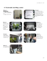
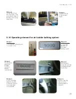
5.6 Fan motor

Picture 2: 

Additional parts:  

1 x fan motor 

Picture 1: 

Required tools: 

1 x Allen wrench 2.5 mm 

1 x open-end wrench 10 mm 

Picture 3: 

Open the distributor 

unit and unclamp the 

line for the fan motor. 

Picture 4: 

Open the distributor 

unit and unclamp the 

line for the fan motor.

Summary of Contents for 278300

Page 1: ...Edition V 1 6 EN Technical Changes reserved 09 09 2014 Service Manual for AVERO Premium tub 190 Part No 278400 AVERO Premium tub 175 Part No 278300 Picture shows AVERO Premium 190 Part No 278400...

Page 2: ...hermostat 24 5 11 Disinfectant container 25 5 12 Air nozzles without fan hose 26 5 13 Air distributor 28 5 14 Operating element for air bubble bathing system 29 5 15 Operating element for automatic wa...

Page 3: ...ooting Customer Service 43 7 1 Troubleshooting 43 7 2 Customer Service 44 8 Appendix 45 8 1 Technical Data 45 8 2 Icons and symbols used 47 8 3 Declaration of Conformity 48 8 4 Accessories lifting tub...

Page 4: ...manufacturer of the tub shall only be responsible for the safety and reliability of the device if a the installation has been done by an authorized BEKA Hospitec distributor b the respective space is...

Page 5: ...intervals of 12 months Performance of the safety technology inspections and maintenance must be recorded An inspection must be arranged at expiration date as per the red test sticker on the reverse si...

Page 6: ...3 Dimensions 3 1 AVERO Premium 190 mm Prism Medical Ltd V1 2014 6 575 Width inside down 720 Width inside up...

Page 7: ...3 2 AVERO Premium 175 mm Prism Medical Ltd V1 2014 7 575 Width inside down 720 Width inside up...

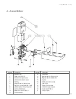
Page 8: ...er 14 Magnet valve for disinfection 4 Armored tube warm water 15 Injector 5 Earthing 16 Distributor Mains supply 6 Magnet valve for hand shower 17 Hoist motor 7 Sensor for mixed water HB WB 18 Sensor...

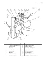
Page 9: ...tomatic tub filling 3 Tub water inlet 11 Inlet temperature thermometer 4 Concealed thermostat with scald 12 Handheld shower protection 5 Disinfection valve 13 Disinfection spray nozzle 6 Tub filling v...

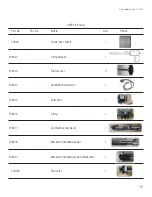
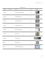
Page 10: ...78411 Control box 120volt 1 278412 Lifting Actuator 1 278413 Tub foot rear 2 278414 Handheld shower wand 1 278415 Solenoid 1 278416 Fitting 1 278417 Disinfection spray wand 1 278418 Bracket for handhe...

Page 11: ...s complete 1 278422 Hose 1 278423 Hose clamps 10 pcs 278424 T piece for hose 5 pcs 278425 Elbow connection Set of 12 278426 Air distributor incl ear hose clips 1 278427 Overflow turning knob 1 278428...

Page 12: ...cture 278431 Cover for backflow preventer 2 278432 Connecting hose 12 4 278433 Connecting hose 20 3 278434 Connecting hose 36 2 278435 Roller for lifting column 4 278436 CSA injector 1 278437 CSA flow...

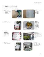
Page 13: ...Additional parts 4 x POM 4 x screws Picture 8 The illustration shows the frame without the POM slide bearing Picture 7 Remove the screw and the right POM Picture 3 Loosen the nuts using the ratchet an...

Page 14: ...screws from the distributor unit Aerospa Picture 4 Remove the cover of the disinfectant container and take the container out from the open back wall Picture 3 Remove all cables from the control Pictu...

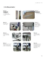
Page 15: ...ct the power supply Picture 4 Disconnect all cables from the control Cable for control cable for lifting motor Picture 5 Loosen the lower screw on the lifting motor Picture 6 Loosen the upper screw on...

Page 16: ...er from the lower motor mount Picture 12 Remove the screw from the lower motor mount and take the lifting motor out of the lifting frame Picture 2 The illustration shows the installed flow meter in th...

Page 17: ...2 connecting hoses from the flow meter Picture 8 The illustration shows the connecting hoses removed from the flow meter Picture 9 Remove the 2 fastening clips from the flow meter Picture 10 You can t...

Page 18: ...line using the pipe wrench Picture 6 Loosen the union nut of the hot water line using the pipe wrench Picture 7 Remove the union nut from the thread of the connection Picture 9 Unscrew the angle conne...

Page 19: ...union nut from the thread of the connection for cold water Picture 13 Remove the union nut from the thread of the connection for hot water 5 6 Fan motor Picture 2 Additional parts 1 x fan motor Pictu...

Page 20: ...cket and the perforated metal strap Picture 5 The illustration shows the fan motor fastened to the mounting bracket with perforated metal strap Picture 7 Remove the perforated metal strap from the fan...

Page 21: ...nit in the retaining plate for disinfectant Picture 2 The illustration shows the control for automatic filling mounted on the disinfectant holder To open the rear wall follow the instructions in point...

Page 22: ...small Picture 4 Using the screwdriver loosen the screw for the plug in contact on the solenoid and pull out the plug in contact Picture 5 Loosen and remove the union nut from the fabric hose Picture 6...

Page 23: ...he screwdriver Picture 5 Pull the adapter fixture out using the pipe wrench Picture 3 Take off the knob by pulling upward Picture 2 The illustration shows the installed fitting group Handheld spray fo...

Page 24: ...rying it out from below with the screwdriver in the recess Picture 6 Remove the sealing sleeve Picture 5 Loosen and remove the locking screw from the thermostat rotary mechanism Picture 3 The illustra...

Page 25: ...er etc can be taken out and replaced 5 11 Disinfectant container Picture 1 Open the back wall of the AVERO Premium as described in point 5 18 Picture 2 The illustration shows the disinfectant containe...

Page 26: ...les without fan hose Picture 1 Required tools 1 x nipper pliers 1 x shears 1 x Loctite sealing compound 1 x pipe wrench without teeth Picture 4 Take off the hose clamp using the nipper pliers Picture...

Page 27: ...rom the hose Picture 8 The illustration shows all the connecting valves screwed on the tub body tub body outside view Picture 9 The illustration shows the connecting valve screwed on Picture 10 Remove...

Page 28: ...necting valve removed from the air nozzle Picture 15 You can take out the air nozzle 5 13 Air distributor Picture 2 Additional parts 1 x air distributor Picture 1 Required tools 1 x nipper pliers 1 x...

Page 29: ...onal parts 1 x operating element for Air bubble bathing system Picture 1 Required tools 1 x screwdriver with extension 1 x socket 10 mm Picture 3 The illustration shows the installed operating element...

Page 30: ...he illustration shows the operating element with threaded connection loosened inside view Picture 3 The illustration shows the operating element for the autom water stop mounted on the control console...

Page 31: ...tom water stop and remove the cable from the distributor unit 5 16 Removal of the bathtub from the lifting frame Picture 1 Required tools 1 x ratchet with extension 1 x socket 10 mm 1 x bit AW 2 5 1 x...

Page 32: ...stening screws right Picture 8 Loosen and remove the upper fastening screws left Picture 9 The illustration shows the lower fastening screws Picture 10 Loosen and remove the upper fastening screws lef...

Page 33: ...e of the sensor and place it at the position of the old sensor 1 x sensor for autom water stop Picture 3 Loosen the sensor using a carpet knife Picture 4 Open the distributor unit in order to unclamp...

Page 34: ...it and clamp the cable of the sensor Then screw on PG threaded connection again 5 18 Opening and closing the rear wall Picture 1 Required tools 1 x screwdriver PH2 Picture 2 Remove all screws 9 pcs fr...

Page 35: ...cture 1 Required tools 1 x Screwdriver PH2 Picture 2 Additional parts 1 x turning knob drain plug set Picture 5 Remove the screw connection Picture 4 Loosen the screw with the screwdriver Remove the t...

Page 36: ...e 2 Additional parts 1 x turning knob set Picture 7 The picture shows the removed drain cover Picture 6 Remove the drain cover Picture 5 Loosen and remove the screw of the drain cover Picture 4 Remove...

Page 37: ...e 3 The picture shows the hand shower holder incl the elbow connection Picture 4 Loosen the headless screw from the hand shower holder Picture 5 Loosen the nut of the hand shower holder Picture 6 The...

Page 38: ...re 1 Additional parts 1 x Hand shower incl hand shower hose Picture 4 The picture shows the unscrewed hand shower hose with the cap nut Picture 2 The picture shows the hand shower Picture 3 Unscrew th...

Page 39: ...connection Picture 2 Additional parts 1 x Hand shower disinfection Picture 1 Required tools 1 x Allen key 2 5 mm Picture 5 The picture shows the elbow connection of the disinfection hand shower Pictur...

Page 40: ...or of the AVERO Premium new Picture 4 The temperature unit can be set from Fahrenheit to C and vice versa by pressing the small black button marked in red in the picture Picture 5 You can insert the t...

Page 41: ...re 3 Loosen and remove all 9 screws of the back cover Picture 2 The picture shows the back cover of the AVERO Premium new Picture 4 The picture shows the removed back cover 485 Millway Ave Concord Ont...

Page 42: ...Prism Medical Ltd V1 2014 6 Periodic Inspection 42...

Page 43: ...b Check cable for damage No water a Check the lock valves of the cold and hot water as well as the pipe interrupter b Check the water inlet filter The automatic filling does not work Disconnect from...

Page 44: ...k that power is supplied The air spa system fails during operation a The air spa system has been used for more than 15 minutes Let it cool down b Overheating due to high ambient temperature Let it coo...

Page 45: ...Weight without water 190 ca 250 kg Weight without water 175 ca 230 kg Weight with water completely filled 190 ca 415kg Weight with water completely filled 175 ca 375kg Capacity without patient 190 ca...

Page 46: ...erating element Accuracy of the display 1 C ENVIRONMENTAL CONDITIONS Operation Temperature range Between 10 C and 40 C Relative humidity Non condensing between 30 and 95 Atmospheric pressure range 800...

Page 47: ...ed on the base frame Application part Type B according to DIN EN 60601 1 No domestic waste Do not put the treatment system and packaging materials into the domestic waste CE mark according to 93 42 EE...

Page 48: ...Avero Premium Disinfection system 278403 Avero Premium Auto Fill 278404 Avero Premium Air jet system 10 jets 278405 Avero Premium Shampoo Bath dispenser system 278410 Avero Premium Jug with disinfecta...

Reviews: