Prism Medical Ltd. V1-2014
30
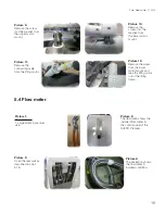
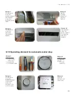
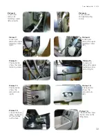
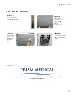
Picture 10:
The illustration
shows the
recess in which
the operating
element is
installed.
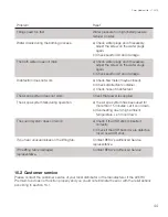
Picture 9:
The illustration
shows the
removal of
the operating
element.
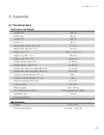
Picture 8:
Take the
operating
element out
straight to
the front.
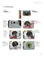
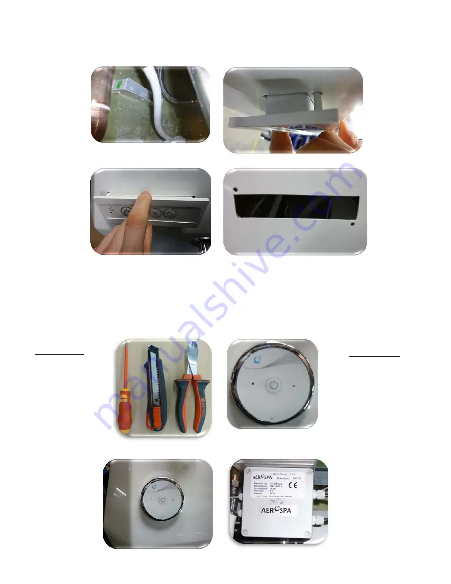
Picture 7:
The illustration
shows the
operating element
with threaded
connection
loosened (inside
view).
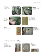
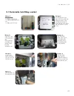
Picture 3:
The illustration
shows the
operating element
for the autom.
water stop
mounted on the
control console.
Picture 1:
Required tools:
1 x slotted screw
driver, small
1 x carpet knife
1 x combination pliers
Picture 4:
Open the
distributor unit
shown here.
Picture 2:
Additional parts:
1 x operating
element
for autom.
water stop
5.15 Operating element for automatic water stop

