5
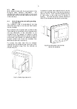
Fig 3
Indicator providing a remote display
4.
INSTALLATION
4.1 Location
BA504G-SS-PM and BA524G-SS-PM indicators
have a 316 stainless steel enclosure.
Both have
IP66 front of panel ingress protection after a 7J
impact and have a thick armoured window which
will withstand a 4J impact.
They are suitable for
exterior mounting in most industrial and marine
environments.
The indicators should be positioned where the
display is not in continuous direct sunlight.
Panel wiring terminals are located on the rear of
the indicator as shown in Fig 6 which has IP20
protection. Terminals 2 and 4 are internally joined
and may be used for linking the return 4/20mA wire
- see Fig 1.
4.2
Installation Procedure
Fig 4 shows the recommended panel cut-out
dimensions and Fig 5 the installation procedure.
The panel should be flat and there should be no
burrs or rough edges on the cut-out.
a. Position the black moulded silicone gasket
onto the indicator's stainless steel casting.
b. Secure the indicator assembly onto the panel
using the four supplied M5 x 16 stainless
steel hexagon headed screws and spring
washers. Ensure that the casting is correctly
positioned in the gasket and that the gasket is
flat and in continuous contact with the panel
before evenly tighten the four screws to
40cN-m.
CAUTION
If
the
instrument
panel
has
a
non-
conductive finish, an earthed ring tag
should be fitted under one of the screw
heads to ensure that the indicator is
earthed.
c. Connect
panel wiring to the indicator
terminals as shown in Fig 6.
Fig 4 Recommended panel cut-out dimensions
Fig 5 BA504G-SS-PM and BA524G-SS-PM
installation procedure.
Fig 6 Terminals and overall dimensions


