Page 2 of 9
Instruction Manual A75 Version 6 19th April 2004
BEKA associates Ltd, Old Charlton Road, Hitchin, Hertfordshire. SG5 2DA. UK. Tel: +44 (0) 1462 438301
1) Unpacking
The packaging for your Advisor A75 includes:
1) An Advisor A75 digital panel meter
2) A pair of panel mounting clips
3) A neoprene sealing gasket
4) Full set of connector blocks
5) A set of self-adhesive engineering unit labels
6) This
instruction
manual
Check your unit against the above parts list to make sure
that nothing has been lost or damaged in transit. Keep the
packing box as this will be useful if in the unlikely event you
need to return the Advisor. If any parts are missing or
damaged, please contact your supplier.
2) Safety and Warnings
The Advisor A75 has been designed and tested in
accordance with the EU directive (73/23/EEC) for Low
Voltage (LVD) apparatus and the EU Directive
(89/336/EEC) for Electromagnetic Compatibility (EMC).
Copies of the certificate of compliance and test reports are
available on request.
It should be noted that the instrument is a panel mounted
meter and after installation only the front panel is intended
for general operator access. Installation must be completed
by authorised and qualified personnel.
To ensure safe operation/installation the following warnings
must be observed.
•
Before installing the meter, ensure the marked
rated voltage agrees with the actual power supply
voltage.
•
A safety earth must be connected to a conductive
panel into which the meter will be installed. A
safety earth must be connected with the AC mains
supply to the instrument.
(If applicable)
•
Do not expose the rear of the meter to rain or
condensing humidity.
•
Do not use the meter in a flammable or explosive
atmosphere.
3)
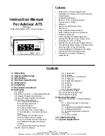
Introduction
The Advisor A75 digital panel meter is one of a family of
Advisor panel meters. The A75 has been designed
specifically to display voltage or current process signals in
engineering units. It is a microprocessor based instrument
and consequently simple to use. The Advisor A75 has a
user selectable input range. The power supply is selected
at the time of ordering. Each Advisor has a display
brightness control and max & min hold already included in
the internal software.
There are also several other options that can be included
with an Advisor including;
•
Dual
Alarms
•
Analogue
Output
(4-20mA)
•
Transducer Power Supply (user selectable, 5,10,12 or
15Vdc)
•
Transmitter Power Supply (24Vdc @22mA)
•
Internal
Calibrator
•
Root
Extractor
•
Tare Function (for weighing applications)
Advisors have been designed to be reliable in harsh
environments. The front is rated with an ingress protection of IP65
and rear of IP20. The programming buttons on the front of the
Advisors are sealed membrane type, thereby allowing the unit to
be kept clean by hosing or wiping down.
4) Electrical Specification
Power Supply
10 to 35Vdc
99 to 132Vac 50/60Hz or
198 to 264Vac 50/60Hz
Power Consumption
4W Max.
Input Range
(user selectable)
0-100mV, 0-200mV, 0-500mV, 0-1V, 0-2V, 0-5V, 1-5V,
0-10V, 0-20mA, 4-20mA, 0-50mA or 10-50mA
Input Impedance
Voltage input > 1 MOhms (>10 Mohms for 0-100mV
and 0-200mV inputs)
Current input < 10 ohms
Isolation
500Vrms between input, power supply and any optional
accessory outputs.
Accessories
(factory fitted)
Alarms (Dual)
Single pole changeover relay contact, 250V @ 5A ac
and 30V @ 5A dc.
Transmitter Power Supply
24Vdc @ 22mA short circuit protected
Transducer Supply Output
Selectable output 5,10,12 or 15Vdc @ 22mA, short
circuit protected. Drift < 100ppm/
o
C
Analogue Output (4-20mA)
500 Ohms maximum load.
5)
Dimensions
Recommended panel cut-out: (dimensions in mm)
DIN43 700. 92.0+0.8/-0.0 x 45+0.6/-0.0
To achieve an IP65 seal between the instrument and the panel
90.0+0.5/-0.0 x 43.5+0.5/-0.0
CAUTION:
Read instructions prior to
installation and operation.
CAUTION:
Risk of electric shock


