Page 9 of 9
Instruction Manual A75 Version 6 19th April 2004
BEKA associates Ltd, Old Charlton Road, Hitchin, Hertfordshire. SG5 2DA. UK. Tel: +44 (0) 1462 438301
4 seconds. The tare value is stored even if there is a power
failure.
10) - Troubleshooting
There is no display.
Check all the connections are correctly
made and check the power supply for the correct rating.
I have changed the input type, and no longer have a
sensible reading.
Make sure you have changed over the
input connectors for example, changing an input from 4-20mA
to 0-10V will require the input to be changed from terminals
3&4 to 1&4.
The display is not very bright/too bright.
Adjust the
brightness by pressing and holding the up or down button.
(Section 9.1.3)
Display doesn’t seem to be responding to a change of
input signal.
Check the input signal. It may also be possible
that someone has accidentally re-calibrated the unit to display
the same value over the full input range – check the span and
zero settings in the “cAL” parameters (Section 8.5.6) – if
necessary re-calibrate with the “Int” (internal) settings.
Alternatively, the internal references may have been
accidentally reset – re-program them. (Section 8.5.7)
None of the pushbuttons seem to be working.
It may be
that the pushbuttons have been disabled (i.e. anti-tamper
function has been switched on). Enter the button re-enable
sequence. (Section 8.7)
The display is too “jumpy”.
Check the signal source, it may
be noisy. If the signal source cannot be “damped” down,
change the resolution of the Advisor. (Section 8.5.2)
I’ve forgotten my password – how do I get access ?
Enter
“FPAc” (the emergency code – mnemonic “Forgotten Panel
Access Code”) and re-enter a new password in “F.PAn” menu
option. (Section 8.5.9)
The alarms are on when they should be off and vice
versa.
Check the high and low alarm settings (Section 8.6.4)
and/or check you have the normally energized (“nE”)
parameter correctly programmed (Section 8.6.5)
The analogue output current doesn’t seem to be correct.
The analogue output can be adjusted. (Section 8.5.8)
The transducer supply output is higher than expected.
Remember, the transducer supply output is a 4 wire output
i.e. 2 supply lines and 2 sense lines. The sense lines must be
connected either directly to the sensor or to the supply
outputs otherwise the Advisor will “hunt” for a sensor and the
output voltage will seem to be excessive. (See section 8.8)
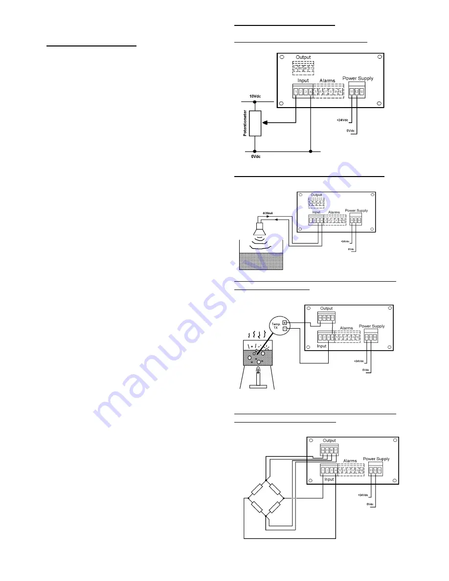
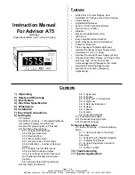
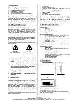
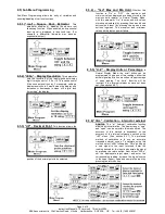
11) Typical Applications
A Position Sensor (0-10V input signal)
Tank Level Display (4/20mA Active Sensor)
Transmitter has its own power supply
Temperature Display (4/20mA Passive – Loop-
powered Transmitter)
24Vdc transmitter power supply option fitted
Weight Display (15Vdc Transducer supply
output, 0-100mV input range)
Transducer power supply fitted.


